Cirkit Designer Logo
Cirkit Designer
Your all-in-one circuit design IDE
Home / 
Component Documentation

How to Use SOFAR 3K~6KTLM-G3: Examples, Pinouts, and Specs

Image of SOFAR 3K~6KTLM-G3
Cirkit Designer LogoDesign with SOFAR 3K~6KTLM-G3 in Cirkit Designer

Introduction

The SOFAR 3K~6KTLM-G3 is a high-performance solar inverter designed to convert direct current (DC) generated by solar panels into alternating current (AC) suitable for residential and commercial use. With a power range of 3 to 6 kilowatts, this inverter is ideal for small to medium-sized solar energy systems. It features advanced monitoring capabilities, high efficiency, and robust safety mechanisms, making it a reliable choice for sustainable energy solutions.

Explore Projects Built with SOFAR 3K~6KTLM-G3

Use Cirkit Designer to design, explore, and prototype these projects online. Some projects support real-time simulation. Click "Open Project" to start designing instantly!
STM32F103C8T6-Based Water Level Monitoring and Communication System with SIM900A and LoRa Connectivity
Image of water level: A project utilizing SOFAR 3K~6KTLM-G3 in a practical application
This circuit features a microcontroller (STM32F103C8T6) interfaced with a SIM900A GSM module, an HC-SR04 ultrasonic sensor, a water level sensor, and a LoRa Ra-02 SX1278 module for long-range communication. The STM32F103C8T6 is configured to communicate with the GSM module and LoRa module via serial connections, and it reads data from the ultrasonic and water level sensors. An FTDI Programmer is connected for programming and serial communication with the microcontroller.
Cirkit Designer LogoOpen Project in Cirkit Designer
Arduino UNO with A9G GSM/GPRS and Dual VL53L1X Distance Sensors
Image of TED CIRCUIT : A project utilizing SOFAR 3K~6KTLM-G3 in a practical application
This circuit features an Arduino UNO microcontroller interfaced with an A9G GSM/GPRS+GPS/BDS module and two VL53L1X time-of-flight distance sensors. The A9G module is connected to the Arduino via serial communication for GPS and GSM functionalities, while both VL53L1X sensors are connected through I2C with shared SDA and SCL lines and individual SHUT pins for selective sensor activation. The Arduino is programmed to control these peripherals, although the specific functionality is not detailed in the provided code.
Cirkit Designer LogoOpen Project in Cirkit Designer
Solar-Powered GSM/GPRS+GPS Tracker with Seeeduino XIAO
Image of SOS System : A project utilizing SOFAR 3K~6KTLM-G3 in a practical application
This circuit features an Ai Thinker A9G development board for GSM/GPRS and GPS/BDS connectivity, interfaced with a Seeeduino XIAO microcontroller for control and data processing. A solar cell, coupled with a TP4056 charging module, charges a 3.3V battery, which powers the system through a 3.3V regulator ensuring stable operation. The circuit likely serves for remote data communication and location tracking, with the capability to be powered by renewable energy and interfaced with additional sensors or input devices via the Seeeduino XIAO.
Cirkit Designer LogoOpen Project in Cirkit Designer
Cellular-Enabled IoT Device with Real-Time Clock and Power Management
Image of LRCM PHASE 2 BASIC: A project utilizing SOFAR 3K~6KTLM-G3 in a practical application
This circuit features a LilyGo-SIM7000G module for cellular communication and GPS functionality, interfaced with an RTC DS3231 for real-time clock capabilities. It includes voltage sensing through two voltage sensor modules, and uses an 8-channel opto-coupler for isolating different parts of the circuit. Power management is handled by a buck converter connected to a DC power source and batteries, with a fuse for protection and a rocker switch for on/off control. Additionally, there's an LED for indication purposes.
Cirkit Designer LogoOpen Project in Cirkit Designer

Explore Projects Built with SOFAR 3K~6KTLM-G3

Use Cirkit Designer to design, explore, and prototype these projects online. Some projects support real-time simulation. Click "Open Project" to start designing instantly!
Image of water level: A project utilizing SOFAR 3K~6KTLM-G3 in a practical application
STM32F103C8T6-Based Water Level Monitoring and Communication System with SIM900A and LoRa Connectivity
This circuit features a microcontroller (STM32F103C8T6) interfaced with a SIM900A GSM module, an HC-SR04 ultrasonic sensor, a water level sensor, and a LoRa Ra-02 SX1278 module for long-range communication. The STM32F103C8T6 is configured to communicate with the GSM module and LoRa module via serial connections, and it reads data from the ultrasonic and water level sensors. An FTDI Programmer is connected for programming and serial communication with the microcontroller.
Cirkit Designer LogoOpen Project in Cirkit Designer
Image of TED CIRCUIT : A project utilizing SOFAR 3K~6KTLM-G3 in a practical application
Arduino UNO with A9G GSM/GPRS and Dual VL53L1X Distance Sensors
This circuit features an Arduino UNO microcontroller interfaced with an A9G GSM/GPRS+GPS/BDS module and two VL53L1X time-of-flight distance sensors. The A9G module is connected to the Arduino via serial communication for GPS and GSM functionalities, while both VL53L1X sensors are connected through I2C with shared SDA and SCL lines and individual SHUT pins for selective sensor activation. The Arduino is programmed to control these peripherals, although the specific functionality is not detailed in the provided code.
Cirkit Designer LogoOpen Project in Cirkit Designer
Image of SOS System : A project utilizing SOFAR 3K~6KTLM-G3 in a practical application
Solar-Powered GSM/GPRS+GPS Tracker with Seeeduino XIAO
This circuit features an Ai Thinker A9G development board for GSM/GPRS and GPS/BDS connectivity, interfaced with a Seeeduino XIAO microcontroller for control and data processing. A solar cell, coupled with a TP4056 charging module, charges a 3.3V battery, which powers the system through a 3.3V regulator ensuring stable operation. The circuit likely serves for remote data communication and location tracking, with the capability to be powered by renewable energy and interfaced with additional sensors or input devices via the Seeeduino XIAO.
Cirkit Designer LogoOpen Project in Cirkit Designer
Image of LRCM PHASE 2 BASIC: A project utilizing SOFAR 3K~6KTLM-G3 in a practical application
Cellular-Enabled IoT Device with Real-Time Clock and Power Management
This circuit features a LilyGo-SIM7000G module for cellular communication and GPS functionality, interfaced with an RTC DS3231 for real-time clock capabilities. It includes voltage sensing through two voltage sensor modules, and uses an 8-channel opto-coupler for isolating different parts of the circuit. Power management is handled by a buck converter connected to a DC power source and batteries, with a fuse for protection and a rocker switch for on/off control. Additionally, there's an LED for indication purposes.
Cirkit Designer LogoOpen Project in Cirkit Designer

Common Applications and Use Cases

  • Residential solar energy systems for powering household appliances.
  • Commercial solar installations for small businesses.
  • Grid-tied solar systems to reduce electricity bills and feed excess energy back to the grid.
  • Backup power systems when paired with energy storage solutions.

Technical Specifications

Key Technical Details

Parameter Value
Power Output Range 3 kW to 6 kW
Input Voltage Range (DC) 160 V to 1000 V
Maximum Input Current 12.5 A per MPPT
Number of MPPTs (Trackers) 2
Output Voltage (AC) 230 V (Single Phase)
Output Frequency 50 Hz / 60 Hz
Efficiency Up to 98.6%
Communication Interfaces Wi-Fi, RS485, and Ethernet
Operating Temperature -25°C to +60°C
Protection Rating IP65 (Outdoor Rated)

Pin Configuration and Descriptions

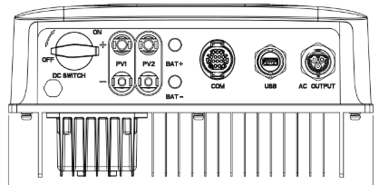
The SOFAR 3K~6KTLM-G3 features multiple input and output terminals for DC and AC connections, as well as communication ports. Below is a summary of the key connections:

DC Input Terminals

Pin Name Description
PV+ Positive terminal for solar panel input
PV- Negative terminal for solar panel input

AC Output Terminals

Pin Name Description
L Live wire for AC output
N Neutral wire for AC output
PE Protective Earth (Ground)

Communication Ports

Port Name Description
RS485 For external monitoring and control
Wi-Fi Module Wireless communication for monitoring
Ethernet Wired communication for monitoring

Usage Instructions

How to Use the Component in a Circuit

  1. DC Input Connection: Connect the positive (PV+) and negative (PV-) terminals of the inverter to the corresponding terminals of the solar panel array. Ensure the input voltage is within the specified range (160 V to 1000 V).
  2. AC Output Connection: Connect the live (L), neutral (N), and protective earth (PE) terminals to the building's electrical distribution system or grid connection.
  3. Communication Setup: Use the RS485, Wi-Fi, or Ethernet port to connect the inverter to a monitoring system or app for real-time performance tracking.
  4. Power On: Once all connections are secure, switch on the inverter. The device will automatically start tracking the maximum power point (MPPT) and begin converting DC to AC.

Important Considerations and Best Practices

  • Safety First: Always disconnect the inverter from the power supply before performing any maintenance or wiring changes.
  • Proper Grounding: Ensure the PE terminal is securely connected to the ground to prevent electrical hazards.
  • Voltage Matching: Verify that the solar panel array's voltage and current are within the inverter's input specifications.
  • Monitoring: Use the manufacturer's app or software to monitor the inverter's performance and detect any issues early.
  • Firmware Updates: Regularly update the inverter's firmware to ensure optimal performance and compatibility with new technologies.

Arduino Integration Example

While the SOFAR 3K~6KTLM-G3 is not directly compatible with Arduino for control purposes, it can be monitored using an RS485-to-UART module. Below is an example of how to read data from the inverter using an Arduino UNO:

#include <ModbusMaster.h>

// Instantiate ModbusMaster object
ModbusMaster node;

void setup() {
  Serial.begin(9600); // Initialize serial communication
  node.begin(1, Serial); // Set Modbus slave ID to 1 and use Serial for communication
}

void loop() {
  uint8_t result;
  uint16_t data[6];

  // Read holding registers starting at address 0x0000
  result = node.readHoldingRegisters(0x0000, 6);

  if (result == node.ku8MBSuccess) {
    // Print the retrieved data
    for (int i = 0; i < 6; i++) {
      Serial.print("Register ");
      Serial.print(i);
      Serial.print(": ");
      Serial.println(node.getResponseBuffer(i));
    }
  } else {
    Serial.println("Failed to read data from inverter.");
  }

  delay(1000); // Wait 1 second before the next read
}

Note: Ensure the RS485-to-UART module is properly connected to the Arduino and the inverter's RS485 port. Refer to the inverter's communication protocol documentation for register addresses and data formats.


Troubleshooting and FAQs

Common Issues and Solutions

  1. Inverter Does Not Start

    • Cause: Insufficient DC input voltage.
    • Solution: Check the solar panel array's voltage and ensure it meets the inverter's minimum input requirement (160 V).
  2. Low Efficiency

    • Cause: Incorrect MPPT configuration or shading on solar panels.
    • Solution: Ensure the solar panels are clean and free from obstructions. Verify the MPPT settings.
  3. Communication Failure

    • Cause: Faulty RS485 or Wi-Fi connection.
    • Solution: Check the communication cables and ensure the Wi-Fi module is properly configured.
  4. Overheating

    • Cause: Poor ventilation or high ambient temperature.
    • Solution: Install the inverter in a well-ventilated area and ensure the ambient temperature does not exceed 60°C.

FAQs

  • Q: Can the inverter operate without a grid connection?
    A: No, the SOFAR 3K~6KTLM-G3 is designed for grid-tied systems and requires a grid connection to function.

  • Q: How do I update the firmware?
    A: Use the manufacturer's app or software to download and install the latest firmware via the Wi-Fi or Ethernet connection.

  • Q: What is the warranty period for this inverter?
    A: The standard warranty period is typically 5 years, but this may vary depending on the region and distributor.

  • Q: Can I use this inverter with a battery storage system?
    A: Yes, but additional components such as a hybrid inverter or battery management system may be required.


This concludes the documentation for the SOFAR 3K~6KTLM-G3 solar inverter. For further assistance, refer to the manufacturer's user manual or contact technical support.