How to Use PDC004-PD PD Decoy Module 12V: Examples, Pinouts, and Specs
Introduction
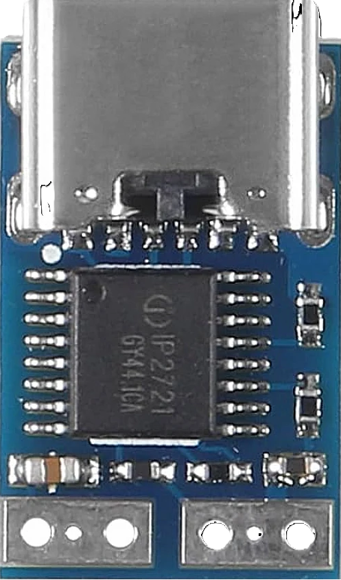
The PDC004-PD PD Decoy Module 12V, manufactured by Hexonix, is a specialized electronic component designed to simulate a power draw in a 12V system. This module is commonly used for testing and troubleshooting purposes in power delivery (PD) systems, ensuring that devices and circuits can handle specific power loads without requiring actual end-use devices. Its compact design and reliable performance make it an essential tool for engineers and hobbyists working with USB-C PD or other 12V power systems.
Explore Projects Built with PDC004-PD PD Decoy Module 12V


Explore Projects Built with PDC004-PD PD Decoy Module 12V
Common Applications and Use Cases
- Testing USB-C Power Delivery (PD) adapters and chargers.
- Simulating a 12V load for power supply validation.
- Troubleshooting power delivery circuits in development or repair.
- Educational purposes for understanding power delivery systems.
Technical Specifications
The following table outlines the key technical details of the PDC004-PD module:
| Parameter | Specification |
|---|---|
| Manufacturer | Hexonix |
| Part ID | PDC004 |
| Input Voltage Range | 5V to 20V (USB-C PD) |
| Output Voltage | 12V (fixed) |
| Maximum Current Draw | 3A |
| Power Rating | 36W |
| Connector Type | USB-C Female |
| Dimensions | 25mm x 20mm x 10mm |
| Operating Temperature | -20°C to 60°C |
| Weight | 10g |
Pin Configuration and Descriptions
The PDC004-PD module does not have traditional pins but instead uses a USB-C female connector. Below is a description of the key connections:
| Pin/Connection | Description |
|---|---|
| VBUS | Power input from the USB-C source (5V to 20V). |
| GND | Ground connection for the power source. |
| CC1/CC2 | Configuration channel pins for USB-C PD negotiation. |
| Output (12V) | Fixed 12V output provided by the module. |
Usage Instructions
How to Use the PDC004-PD in a Circuit
Connect the Module to a Power Source:
Plug the USB-C female connector of the PDC004-PD module into a USB-C PD power source capable of delivering 12V. Ensure the power source supports the required voltage and current specifications.Verify the Output:
Use a multimeter to confirm that the module outputs a stable 12V. This step ensures proper operation before connecting any load.Connect the Load:
Attach the device or circuit you wish to test to the module's output terminals. Ensure the load does not exceed the module's maximum current rating of 3A.Monitor the System:
Observe the behavior of the connected load and the power source. The module will simulate a 12V power draw, allowing you to test the system's performance.
Important Considerations and Best Practices
- Power Source Compatibility: Ensure the USB-C power source supports Power Delivery (PD) and can negotiate a 12V output.
- Heat Dissipation: The module may generate heat during operation, especially at higher currents. Use proper ventilation or a heatsink if necessary.
- Avoid Overloading: Do not exceed the maximum current rating of 3A, as this may damage the module or connected devices.
- Polarity: Always verify the polarity of the output connections to avoid damaging the load.
Example: Using the PDC004-PD with an Arduino UNO
The PDC004-PD can be used to power an Arduino UNO via its VIN pin. Below is an example setup:
- Connect the PDC004-PD module's output to the VIN and GND pins of the Arduino UNO.
- Ensure the USB-C power source is connected and delivering 12V.
- Upload the following code to the Arduino UNO to blink an LED:
// Simple LED Blink Example for Arduino UNO
// This code assumes an LED is connected to pin 13.

void setup() {
  pinMode(13, OUTPUT); // Set pin 13 as an output
}

void loop() {
  digitalWrite(13, HIGH); // Turn the LED on
  delay(1000);            // Wait for 1 second
  digitalWrite(13, LOW);  // Turn the LED off
  delay(1000);            // Wait for 1 second
}
Troubleshooting and FAQs
Common Issues and Solutions
No Output Voltage:
- Cause: The USB-C power source may not support 12V PD or is not negotiating correctly.
- Solution: Verify that the power source supports 12V PD and is properly connected.
Overheating:
- Cause: The module is operating at or near its maximum current rating without adequate cooling.
- Solution: Reduce the load or improve ventilation around the module.
Load Not Functioning Properly:
- Cause: The load may require more current than the module can provide.
- Solution: Ensure the load's current requirements do not exceed 3A.
Intermittent Operation:
- Cause: Poor connection between the USB-C power source and the module.
- Solution: Check the USB-C cable and connectors for damage or loose connections.
FAQs
Q: Can the PDC004-PD output other voltages besides 12V?
A: No, the module is designed to output a fixed 12V when connected to a compatible USB-C PD power source.
Q: Is the module safe to use with sensitive electronics?
A: Yes, as long as the load does not exceed the module's current rating and proper connections are made.
Q: Can I use this module with a non-PD USB-C power source?
A: No, the module requires a USB-C PD power source capable of negotiating a 12V output.
Q: Does the module have built-in overcurrent protection?
A: The module relies on the USB-C power source's protection features. Ensure the power source has adequate safety mechanisms.