How to Use 10A Motor Driver: Examples, Pinouts, and Specs
Introduction
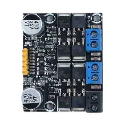
The 10A Motor Driver is a robust electronic component designed to control DC motors with a maximum current of 10A. It supports bidirectional motor control and speed regulation, making it an essential component for robotics, automation systems, and other motor-driven applications. This motor driver is ideal for projects requiring high current handling and precise motor control.
Explore Projects Built with 10A Motor Driver


Explore Projects Built with 10A Motor Driver
Common Applications
- Robotics (e.g., controlling robot wheels or arms)
- Automation systems (e.g., conveyor belts, actuators)
- Electric vehicles and carts
- Industrial machinery
- DIY projects involving high-power DC motors
Technical Specifications
The following table outlines the key technical details of the 10A Motor Driver:
| Parameter | Value |
|---|---|
| Operating Voltage | 6V to 30V |
| Maximum Current | 10A continuous, 15A peak |
| Control Logic Voltage | 3.3V to 5V |
| PWM Frequency | Up to 20 kHz |
| Motor Channels | 2 (dual-channel) |
| Control Modes | Bidirectional control, speed control via PWM |
| Protection Features | Overcurrent, overtemperature, and short-circuit protection |
Pin Configuration and Descriptions
The 10A Motor Driver typically has the following pin layout:
Power and Motor Connections
| Pin Name | Description |
|---|---|
| VCC | Power supply input (6V to 30V) |
| GND | Ground connection |
| OUT1 | Motor A output terminal 1 |
| OUT2 | Motor A output terminal 2 |
| OUT3 | Motor B output terminal 1 |
| OUT4 | Motor B output terminal 2 |
Control Pins
| Pin Name | Description |
|---|---|
| ENA | Enable pin for Motor A (active HIGH) |
| ENB | Enable pin for Motor B (active HIGH) |
| IN1 | Control input 1 for Motor A |
| IN2 | Control input 2 for Motor A |
| IN3 | Control input 1 for Motor B |
| IN4 | Control input 2 for Motor B |
| PWM_A | PWM input for speed control of Motor A |
| PWM_B | PWM input for speed control of Motor B |
Usage Instructions
How to Use the 10A Motor Driver in a Circuit
- Power Supply: Connect the VCC pin to a power source (6V to 30V) and the GND pin to ground. Ensure the power supply can handle the current requirements of the motors.
- Motor Connections: Connect the motor terminals to the OUT1/OUT2 pins (Motor A) and OUT3/OUT4 pins (Motor B).
- Control Pins: Use the IN1, IN2, IN3, and IN4 pins to control the direction of the motors. Apply a HIGH or LOW signal to these pins based on the desired direction.
- Speed Control: Connect a PWM signal to the PWM_A and PWM_B pins to regulate the speed of Motor A and Motor B, respectively.
- Enable Pins: Ensure the ENA and ENB pins are set HIGH to enable the motors.
Important Considerations
- Heat Dissipation: The motor driver may heat up during operation. Use a heat sink or active cooling if necessary.
- Current Limits: Do not exceed the maximum continuous current rating of 10A to avoid damage.
- Power Supply: Use a stable power supply with sufficient current capacity to handle the motors and the driver.
- Logic Voltage: Ensure the control logic voltage (3.3V or 5V) matches the microcontroller or control circuit.
Example: Connecting to an Arduino UNO
Below is an example of how to control a single motor using the 10A Motor Driver and an Arduino UNO:
// Define motor control pins
#define ENA 9    // Enable pin for Motor A
#define IN1 7    // Control pin 1 for Motor A
#define IN2 8    // Control pin 2 for Motor A

void setup() {
  // Set motor control pins as outputs
  pinMode(ENA, OUTPUT);
  pinMode(IN1, OUTPUT);
  pinMode(IN2, OUTPUT);

  // Initialize motor in stopped state
  digitalWrite(IN1, LOW);
  digitalWrite(IN2, LOW);
  analogWrite(ENA, 0); // Set speed to 0
}

void loop() {
  // Example: Rotate motor forward at 50% speed
  digitalWrite(IN1, HIGH);
  digitalWrite(IN2, LOW);
  analogWrite(ENA, 128); // 50% duty cycle (0-255)

  delay(2000); // Run for 2 seconds

  // Example: Rotate motor backward at 75% speed
  digitalWrite(IN1, LOW);
  digitalWrite(IN2, HIGH);
  analogWrite(ENA, 192); // 75% duty cycle

  delay(2000); // Run for 2 seconds

  // Stop the motor
  digitalWrite(IN1, LOW);
  digitalWrite(IN2, LOW);
  analogWrite(ENA, 0); // Set speed to 0

  delay(2000); // Wait for 2 seconds
}
Troubleshooting and FAQs
Common Issues
Motor Not Running
- Cause: ENA or ENB pin is not set HIGH.
- Solution: Ensure the enable pins are set HIGH to activate the motor.
Motor Running in the Wrong Direction
- Cause: Incorrect IN1/IN2 or IN3/IN4 pin configuration.
- Solution: Swap the HIGH/LOW signals on the control pins to reverse the direction.
Overheating
- Cause: Prolonged operation at high current or insufficient cooling.
- Solution: Add a heat sink or active cooling to the motor driver.
PWM Not Controlling Speed
- Cause: Incorrect PWM signal or frequency.
- Solution: Verify the PWM signal is within the supported frequency range (up to 20 kHz).
FAQs
Can I use this motor driver with a 3.3V microcontroller?
- Yes, the control logic supports both 3.3V and 5V levels.
What happens if the current exceeds 10A?
- The motor driver includes overcurrent protection, but prolonged overcurrent may damage the component. Always stay within the rated limits.
Can I control two motors independently?
- Yes, the dual-channel design allows independent control of two motors.
What type of motors can I use with this driver?
- The 10A Motor Driver is compatible with brushed DC motors.
By following this documentation, you can effectively integrate the 10A Motor Driver into your projects and troubleshoot common issues with ease.