How to Use MAX31865: Examples, Pinouts, and Specs
Introduction
The MAX31865 is a precision temperature sensor interface IC specifically designed for RTD (Resistance Temperature Detector) sensors. It simplifies the process of interfacing RTDs with microcontrollers by providing a digital output via an SPI interface. The IC supports both 2-wire, 3-wire, and 4-wire RTD configurations, making it versatile for a wide range of applications. Additionally, it features built-in fault detection, programmable settings, and high accuracy, making it ideal for industrial, scientific, and environmental monitoring systems.
Explore Projects Built with MAX31865


Explore Projects Built with MAX31865
Common Applications
- Industrial temperature monitoring and control
- Scientific instrumentation
- Environmental monitoring systems
- HVAC systems
- Medical devices requiring precise temperature measurements
Technical Specifications
Below are the key technical details of the MAX31865:
| Parameter | Value |
|---|---|
| Supply Voltage (VDD) | 3.0V to 3.6V |
| Operating Temperature Range | -40°C to +125°C |
| RTD Compatibility | PT100, PT1000 |
| RTD Configuration | 2-wire, 3-wire, 4-wire |
| Communication Interface | SPI (Serial Peripheral Interface) |
| Fault Detection | Open/short circuit detection, over/under voltage |
| Input Impedance | > 1MΩ |
| Power Consumption | 5.25mW (typical) |
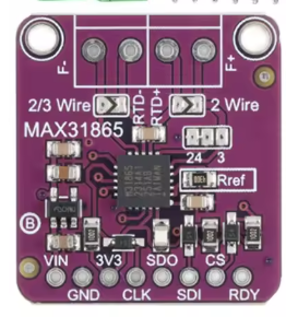
Pin Configuration and Descriptions
The MAX31865 is available in a 20-pin TSSOP package. Below is the pin configuration:
| Pin Number | Pin Name | Description |
|---|---|---|
| 1 | VDD | Power supply input (3.0V to 3.6V). |
| 2 | GND | Ground connection. |
| 3 | CS | Chip Select (active low). Used to enable SPI communication. |
| 4 | SCLK | SPI Clock input. |
| 5 | SDI | SPI Data Input. |
| 6 | SDO | SPI Data Output. |
| 7 | RTDIN+ | Positive input for RTD sensor. |
| 8 | RTDIN- | Negative input for RTD sensor. |
| 9 | FORCE+ | Positive force connection for RTD excitation current. |
| 10 | FORCE- | Negative force connection for RTD excitation current. |
| 11-20 | NC | No connection. Leave these pins unconnected. |
Usage Instructions
How to Use the MAX31865 in a Circuit
- Power Supply: Connect the VDD pin to a 3.3V power source and the GND pin to ground.
- RTD Connection:
- For a 2-wire RTD, connect the RTDIN+ and FORCE+ pins together, and RTDIN- and FORCE- pins together.
- For a 3-wire RTD, connect one lead to FORCE+, the second lead to RTDIN+, and the third lead to RTDIN- and FORCE-.
- For a 4-wire RTD, connect each lead to its respective pin (RTDIN+, RTDIN-, FORCE+, FORCE-).
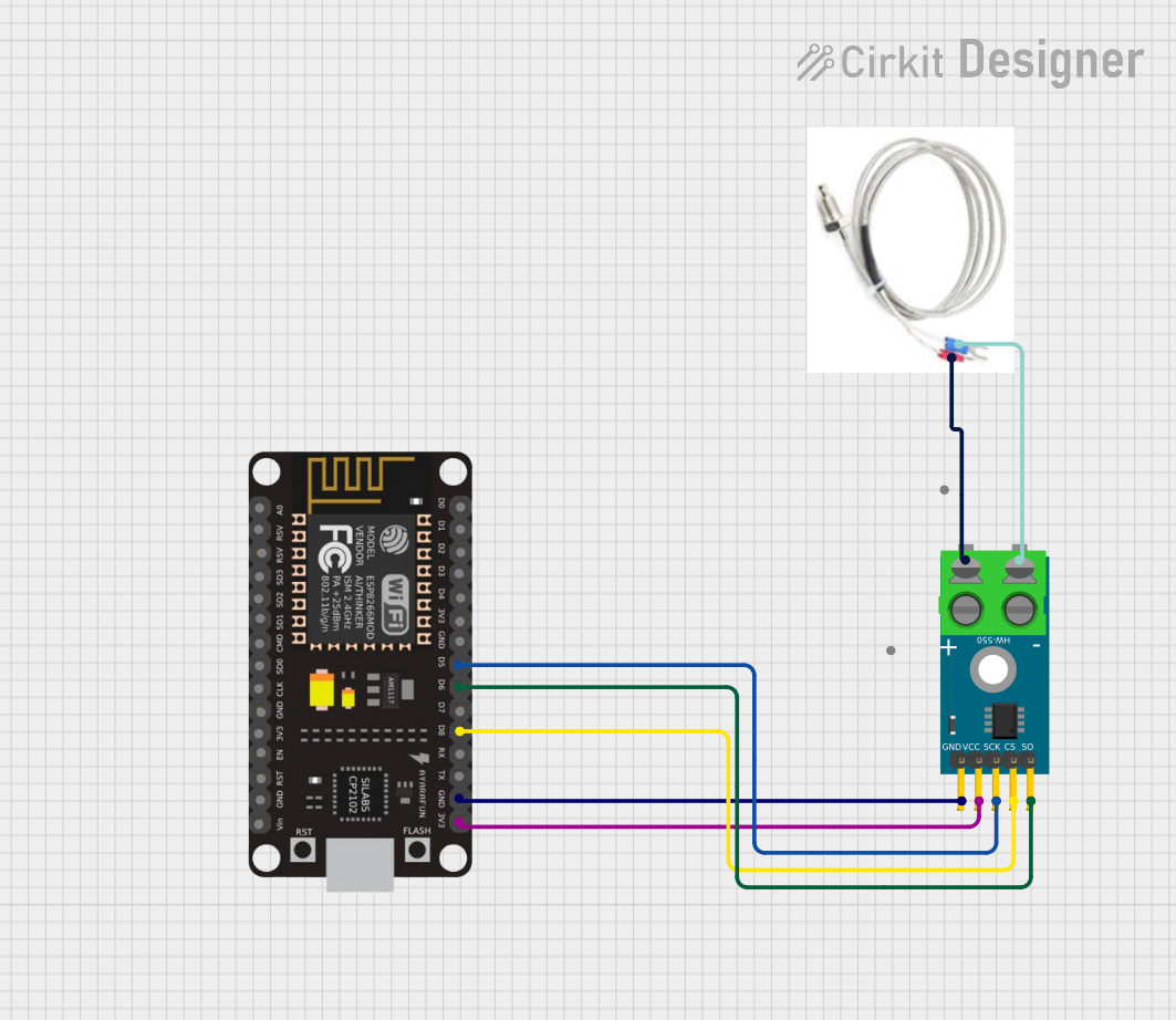
- SPI Communication: Connect the CS, SCLK, SDI, and SDO pins to the corresponding SPI pins on your microcontroller.
- Pull-Up Resistor: Use a pull-up resistor (typically 430Ω for PT100 or 4.3kΩ for PT1000) between FORCE+ and VDD to set the RTD excitation current.
- Fault Detection: Configure the fault detection settings via SPI to monitor for open or short circuits in the RTD.
Best Practices
- Use decoupling capacitors (e.g., 0.1µF and 10µF) between VDD and GND to reduce noise.
- Ensure proper grounding to avoid measurement errors.
- Use shielded cables for RTD connections in noisy environments.
- Calibrate the system for the specific RTD sensor being used to improve accuracy.
Example Code for Arduino UNO
Below is an example of how to interface the MAX31865 with an Arduino UNO to read temperature data from a PT100 RTD:
#include <SPI.h>

// Define MAX31865 pins
#define CS_PIN 10  // Chip Select pin connected to Arduino pin 10

// MAX31865 registers
#define CONFIG_REG 0x00
#define RTD_MSB_REG 0x01
#define RTD_LSB_REG 0x02

void setup() {
  // Initialize SPI and Serial communication
  SPI.begin();
  Serial.begin(9600);

  // Configure the MAX31865
  pinMode(CS_PIN, OUTPUT);
  digitalWrite(CS_PIN, HIGH); // Set CS high to disable the chip

  // Write configuration to MAX31865
  writeRegister(CONFIG_REG, 0xC2); // Enable Vbias, auto conversion, 3-wire RTD
}

void loop() {
  // Read RTD data
  uint16_t rtdData = readRTD();

  // Convert RTD data to resistance
  float resistance = (rtdData >> 1) * 0.03125; // 0.03125Ω per LSB

  // Calculate temperature (simplified for PT100, alpha = 0.00385)
  float temperature = (resistance - 100.0) / (100.0 * 0.00385);

  // Print temperature
  Serial.print("Temperature: ");
  Serial.print(temperature);
  Serial.println(" °C");

  delay(1000); // Wait 1 second before next reading
}

// Function to write to a MAX31865 register
void writeRegister(uint8_t reg, uint8_t value) {
  digitalWrite(CS_PIN, LOW); // Enable the chip
  SPI.transfer(reg | 0x80);  // Set MSB to 1 for write operation
  SPI.transfer(value);
  digitalWrite(CS_PIN, HIGH); // Disable the chip
}

// Function to read RTD data
uint16_t readRTD() {
  digitalWrite(CS_PIN, LOW); // Enable the chip
  SPI.transfer(RTD_MSB_REG); // Start reading from RTD MSB register
  uint8_t msb = SPI.transfer(0x00); // Read MSB
  uint8_t lsb = SPI.transfer(0x00); // Read LSB
  digitalWrite(CS_PIN, HIGH); // Disable the chip

  return (msb << 8) | lsb; // Combine MSB and LSB
}
Troubleshooting and FAQs
Common Issues
No Temperature Reading:
- Ensure the RTD is properly connected to the MAX31865.
- Verify that the SPI connections (CS, SCLK, SDI, SDO) are correct.
- Check the power supply voltage (3.3V) and ensure it is stable.
Incorrect Temperature Values:
- Verify the pull-up resistor value matches the RTD type (e.g., 430Ω for PT100).
- Ensure the RTD configuration (2-wire, 3-wire, or 4-wire) matches the actual setup.
- Calibrate the system for the specific RTD sensor.
Fault Detection Triggered:
- Check for open or short circuits in the RTD wiring.
- Ensure the RTD sensor is functioning correctly.
Tips for Troubleshooting
- Use an oscilloscope to verify SPI signals if communication issues occur.
- Measure the RTD resistance with a multimeter to confirm its functionality.
- Refer to the MAX31865 datasheet for detailed fault codes and troubleshooting steps.