How to Use ESP32: Examples, Pinouts, and Specs
Introduction
The ESP32 is a low-cost, low-power system on a chip (SoC) developed by Espressif Systems. It features integrated Wi-Fi and Bluetooth capabilities, making it an ideal choice for Internet of Things (IoT) applications, smart devices, and embedded systems. The ESP32 is highly versatile, offering dual-core processing, a wide range of GPIO pins, and support for various communication protocols.
Explore Projects Built with ESP32


Explore Projects Built with ESP32
Common Applications and Use Cases
- IoT devices (e.g., smart home systems, sensors, and actuators)
- Wearable technology
- Wireless communication hubs
- Robotics and automation
- Data logging and remote monitoring
- Prototyping and development of connected devices
Technical Specifications
The ESP32 is packed with features that make it a powerful and flexible component for a wide range of applications. Below are its key technical specifications:
Key Technical Details
- Processor: Dual-core Xtensa® 32-bit LX6 microprocessor
- Clock Speed: Up to 240 MHz
- RAM: 520 KB SRAM
- Flash Memory: Typically 4 MB (varies by module)
- Wi-Fi: 802.11 b/g/n (2.4 GHz)
- Bluetooth: v4.2 BR/EDR and BLE
- Operating Voltage: 3.3V
- GPIO Pins: 34 (multipurpose, including ADC, DAC, PWM, I2C, SPI, UART)
- ADC Channels: 18 (12-bit resolution)
- DAC Channels: 2 (8-bit resolution)
- Power Consumption: Ultra-low power in deep sleep mode (~10 µA)
- Operating Temperature: -40°C to 125°C
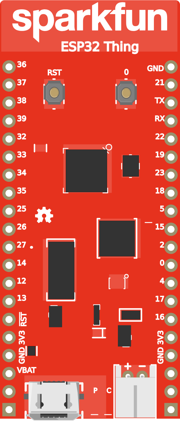
Pin Configuration and Descriptions
The ESP32 has a variety of pins for different functionalities. Below is a table summarizing the key pins and their descriptions:
| Pin Name | Type | Description |
|---|---|---|
| GPIO0 | Input/Output | General-purpose I/O, also used for boot mode selection during startup. |
| GPIO2 | Input/Output | General-purpose I/O, often used as a bootstrapping pin. |
| GPIO12 | Input/Output | General-purpose I/O, can be used for ADC or other functions. |
| GPIO13 | Input/Output | General-purpose I/O, supports PWM and other functions. |
| GPIO15 | Input/Output | General-purpose I/O, supports ADC, PWM, and other functions. |
| EN | Input | Chip enable pin. Pull high to enable the chip, pull low to disable it. |
| 3V3 | Power | 3.3V power supply input/output. |
| GND | Power | Ground connection. |
| TX0 (GPIO1) | Output | UART0 transmit pin, used for serial communication. |
| RX0 (GPIO3) | Input | UART0 receive pin, used for serial communication. |
Note: The ESP32 has many more GPIO pins and features. Refer to the official datasheet for a complete pinout.
Usage Instructions
The ESP32 can be used in a variety of circuits and projects. Below are the steps to get started and some best practices:
How to Use the ESP32 in a Circuit
- Power the ESP32: Connect the 3.3V pin to a stable 3.3V power source and GND to ground.
- Connect to a Computer: Use a USB-to-serial adapter or a development board with a built-in USB interface.
- Program the ESP32: Use the Arduino IDE or Espressif's ESP-IDF to write and upload code to the ESP32.
- Connect Peripherals: Use the GPIO pins to connect sensors, actuators, or other devices. Ensure proper voltage levels.
- Establish Communication: Use Wi-Fi or Bluetooth to connect the ESP32 to a network or other devices.
Important Considerations and Best Practices
- Voltage Levels: The ESP32 operates at 3.3V. Avoid applying 5V to its GPIO pins to prevent damage.
- Boot Mode: Ensure GPIO0 is pulled low during startup to enter programming mode.
- Power Supply: Use a stable power source to avoid unexpected resets or malfunctions.
- Deep Sleep Mode: Use deep sleep mode to conserve power in battery-powered applications.
- Antenna Placement: For optimal Wi-Fi and Bluetooth performance, ensure the onboard antenna is not obstructed.
Example Code for Arduino UNO Integration
Below is an example of how to use the ESP32 with the Arduino IDE to connect to a Wi-Fi network:
#include <WiFi.h> // Include the Wi-Fi library for ESP32

// Replace with your network credentials
const char* ssid = "Your_SSID";
const char* password = "Your_PASSWORD";

void setup() {
  Serial.begin(115200); // Initialize serial communication at 115200 baud
  delay(1000); // Wait for a second to stabilize

  Serial.println("Connecting to Wi-Fi...");
  WiFi.begin(ssid, password); // Start Wi-Fi connection

  // Wait until the ESP32 connects to the Wi-Fi network
  while (WiFi.status() != WL_CONNECTED) {
    delay(500);
    Serial.print(".");
  }

  Serial.println("\nWi-Fi connected!");
  Serial.print("IP Address: ");
  Serial.println(WiFi.localIP()); // Print the assigned IP address
}

void loop() {
  // Add your main code here
}
Note: Replace
Your_SSIDandYour_PASSWORDwith your Wi-Fi network credentials.
Troubleshooting and FAQs
Common Issues and Solutions
- ESP32 Not Connecting to Wi-Fi
- Solution: Double-check the SSID and password. Ensure the Wi-Fi network is active and within range.
- ESP32 Not Entering Programming Mode
- Solution: Ensure GPIO0 is pulled low during startup. Check the USB connection and drivers.
- Random Resets or Instability
- Solution: Use a stable 3.3V power source. Avoid powering the ESP32 directly from a USB port if it cannot supply sufficient current.
- GPIO Pins Not Working as Expected
- Solution: Verify the pin configuration in your code. Some pins have specific functions or limitations.
FAQs
Q: Can the ESP32 operate on 5V?
A: No, the ESP32 operates at 3.3V. Applying 5V to its GPIO pins can damage the chip.Q: How do I update the ESP32 firmware?
A: Use the Espressif Flash Download Tool or the Arduino IDE to upload new firmware.Q: Can the ESP32 be used as a standalone device?
A: Yes, the ESP32 is a complete SoC and can operate independently without additional microcontrollers.Q: How do I reduce power consumption?
A: Use deep sleep mode and disable unused peripherals to minimize power usage.
This documentation provides a comprehensive overview of the ESP32, its features, and how to use it effectively in your projects. For more advanced use cases, refer to the official Espressif documentation.