Cirkit Designer
Your all-in-one circuit design IDE
Home /
Component Documentation
How to Use Voltage Divider Module: Examples, Pinouts, and Specs
Introduction
- A Voltage Divider Module is a circuit component designed to reduce an input voltage to a lower output voltage. It operates using two resistors connected in series, dividing the voltage proportionally based on their resistance values.
- Common applications include:
- Providing a specific voltage level for sensors or microcontrollers.
- Scaling down high voltages for analog-to-digital converters (ADCs).
- Interfacing high-voltage circuits with low-voltage devices.
- Signal conditioning in electronic circuits.
Explore Projects Built with Voltage Divider Module
ADS1115 and ACS712 Current Sensor-Based Voltage and Current Monitoring System

This circuit includes an ADS1115 analog-to-digital converter connected to two voltage divider networks formed by resistors. The voltage dividers are used to scale down the input voltages before they are read by the ADS1115 on channels A0 and A1.
DC-DC Converter and Relay Module Power Distribution System

This circuit consists of a DC-DC converter powering a 6-channel power module, which in turn supplies 5V to a 2-relay module. The power module distributes the converted voltage to the relay module, enabling it to control external devices.
12MHz Crystal Oscillator with 4060 Timer IC and 10k Resistor
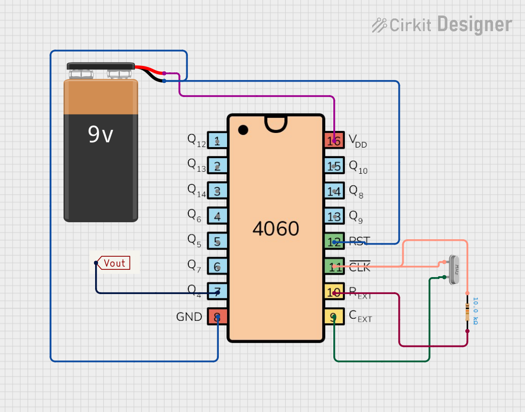
This circuit is a frequency divider using a 4060 binary counter IC and a 12MHz crystal oscillator. It is powered by a 9V battery and provides a divided frequency output at 'Vout'. The 10k Ohm resistor stabilizes the oscillator circuit.
Cellular-Enabled IoT Device with Real-Time Clock and Power Management

This circuit features a LilyGo-SIM7000G module for cellular communication and GPS functionality, interfaced with an RTC DS3231 for real-time clock capabilities. It includes voltage sensing through two voltage sensor modules, and uses an 8-channel opto-coupler for isolating different parts of the circuit. Power management is handled by a buck converter connected to a DC power source and batteries, with a fuse for protection and a rocker switch for on/off control. Additionally, there's an LED for indication purposes.
Explore Projects Built with Voltage Divider Module
ADS1115 and ACS712 Current Sensor-Based Voltage and Current Monitoring System
This circuit includes an ADS1115 analog-to-digital converter connected to two voltage divider networks formed by resistors. The voltage dividers are used to scale down the input voltages before they are read by the ADS1115 on channels A0 and A1.
DC-DC Converter and Relay Module Power Distribution System
This circuit consists of a DC-DC converter powering a 6-channel power module, which in turn supplies 5V to a 2-relay module. The power module distributes the converted voltage to the relay module, enabling it to control external devices.
12MHz Crystal Oscillator with 4060 Timer IC and 10k Resistor
This circuit is a frequency divider using a 4060 binary counter IC and a 12MHz crystal oscillator. It is powered by a 9V battery and provides a divided frequency output at 'Vout'. The 10k Ohm resistor stabilizes the oscillator circuit.
Cellular-Enabled IoT Device with Real-Time Clock and Power Management
This circuit features a LilyGo-SIM7000G module for cellular communication and GPS functionality, interfaced with an RTC DS3231 for real-time clock capabilities. It includes voltage sensing through two voltage sensor modules, and uses an 8-channel opto-coupler for isolating different parts of the circuit. Power management is handled by a buck converter connected to a DC power source and batteries, with a fuse for protection and a rocker switch for on/off control. Additionally, there's an LED for indication purposes.
Technical Specifications
- Input Voltage Range: Typically 0V to 30V (varies by module design).
- Output Voltage Range: Depends on the resistor values; calculated using the formula: [ V_{out} = V_{in} \times \frac{R_2}{R_1 + R_2} ]
- Resistor Tolerance: ±1% to ±5% (depending on the resistors used).
- Power Rating: Determined by the resistors; typically 0.25W to 0.5W.
- Accuracy: Dependent on resistor tolerance and temperature stability.
Pin Configuration and Descriptions
| Pin Name | Description |
|---|---|
VIN |
Input voltage pin. Connect the higher voltage source to this pin. |
GND |
Ground pin. Connect to the ground of the circuit. |
VOUT |
Output voltage pin. Provides the reduced voltage based on the resistor ratio. |
Example Resistor Values
| Resistor R1 (Ω) | Resistor R2 (Ω) | Voltage Divider Ratio (Vout/Vin) |
|---|---|---|
| 10k | 10k | 0.5 |
| 10k | 5k | 0.333 |
| 10k | 1k | 0.091 |
Usage Instructions
Determine the Desired Output Voltage:
- Use the formula ( V_{out} = V_{in} \times \frac{R_2}{R_1 + R_2} ) to calculate the required resistor values.
- Ensure the resistors can handle the power dissipation: ( P = I^2 \times R ).
Connect the Module:
- Connect the input voltage source to the
VINpin. - Connect the ground of the circuit to the
GNDpin. - Measure the reduced voltage at the
VOUTpin.
- Connect the input voltage source to the
Important Considerations:
- Use resistors with low tolerance (e.g., ±1%) for better accuracy.
- Avoid using the module for high-current applications, as the resistors may overheat.
- Ensure the input voltage does not exceed the module's maximum rating.
Using with Arduino UNO:
- The Voltage Divider Module can be used to scale down voltages for the Arduino's ADC, which operates at a maximum input of 5V.
- Example: If measuring a 12V source, use ( R_1 = 10k ) and ( R_2 = 4.7k ) to scale the voltage to approximately 3.83V.
Arduino Code Example
// Arduino code to read the scaled voltage from a Voltage Divider Module
const int voltagePin = A0; // Analog pin connected to VOUT of the module
const float R1 = 10000.0; // Resistor R1 value in ohms
const float R2 = 4700.0;  // Resistor R2 value in ohms

void setup() {
  Serial.begin(9600); // Initialize serial communication
}

void loop() {
  int analogValue = analogRead(voltagePin); // Read the analog value (0-1023)
  float voltage = (analogValue / 1023.0) * 5.0; // Convert to voltage (0-5V)

  // Calculate the input voltage using the voltage divider formula
  float inputVoltage = voltage * (R1 + R2) / R2;

  // Print the input voltage to the Serial Monitor
  Serial.print("Input Voltage: ");
  Serial.print(inputVoltage);
  Serial.println(" V");

  delay(1000); // Wait for 1 second before the next reading
}
Troubleshooting and FAQs
Common Issues
Incorrect Output Voltage:
- Cause: Incorrect resistor values or poor tolerance.
- Solution: Double-check the resistor values and ensure they match the desired ratio.
Overheating Resistors:
- Cause: Excessive current through the resistors.
- Solution: Use resistors with a higher power rating or reduce the input voltage.
No Output Voltage:
- Cause: Loose connections or damaged resistors.
- Solution: Verify all connections and test the resistors with a multimeter.
Arduino Reads Incorrect Voltage:
- Cause: Incorrect scaling in the code or noisy input voltage.
- Solution: Verify the resistor values and ensure proper grounding.
FAQs
Can I use the Voltage Divider Module for high-current applications?
- No, voltage dividers are not suitable for high-current loads as the resistors may overheat or fail.
What resistor values should I use for a specific voltage?
- Use the formula ( V_{out} = V_{in} \times \frac{R_2}{R_1 + R_2} ) to calculate the required resistor values.
Can I use this module with AC voltage?
- No, the module is designed for DC voltage only. For AC applications, additional components like rectifiers are required.
How do I improve the accuracy of the voltage divider?
- Use precision resistors with low tolerance (e.g., ±1%) and ensure stable input voltage.