How to Use T-Beam: Examples, Pinouts, and Specs
Introduction
The T-Beam is an electronic development board that integrates a variety of features including GPS, LoRa communication, and a powerful ESP32 microcontroller. It is designed for IoT applications and is particularly useful for projects that require location tracking and wireless data transmission over long distances. Common applications include asset tracking, remote sensing, and autonomous vehicles.
Explore Projects Built with T-Beam
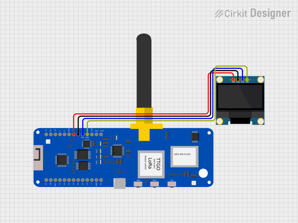
Explore Projects Built with T-Beam
Technical Specifications
General Features
- Microcontroller: ESP32
- Wireless Connectivity: LoRa (Long Range)
- GPS: Onboard GPS module
- Power Options: USB, LiPo battery with charging circuit
- Expansion: GPIO pins available for peripherals
Key Technical Details
- Operating Voltage: 3.3V
- Input Voltage (recommended): 5V via USB or battery
- Digital I/O Pins: 38
- Analog Input Pins: 16
- Flash Memory: 4MB
- SRAM: 520 KB
- Clock Speed: 240 MHz
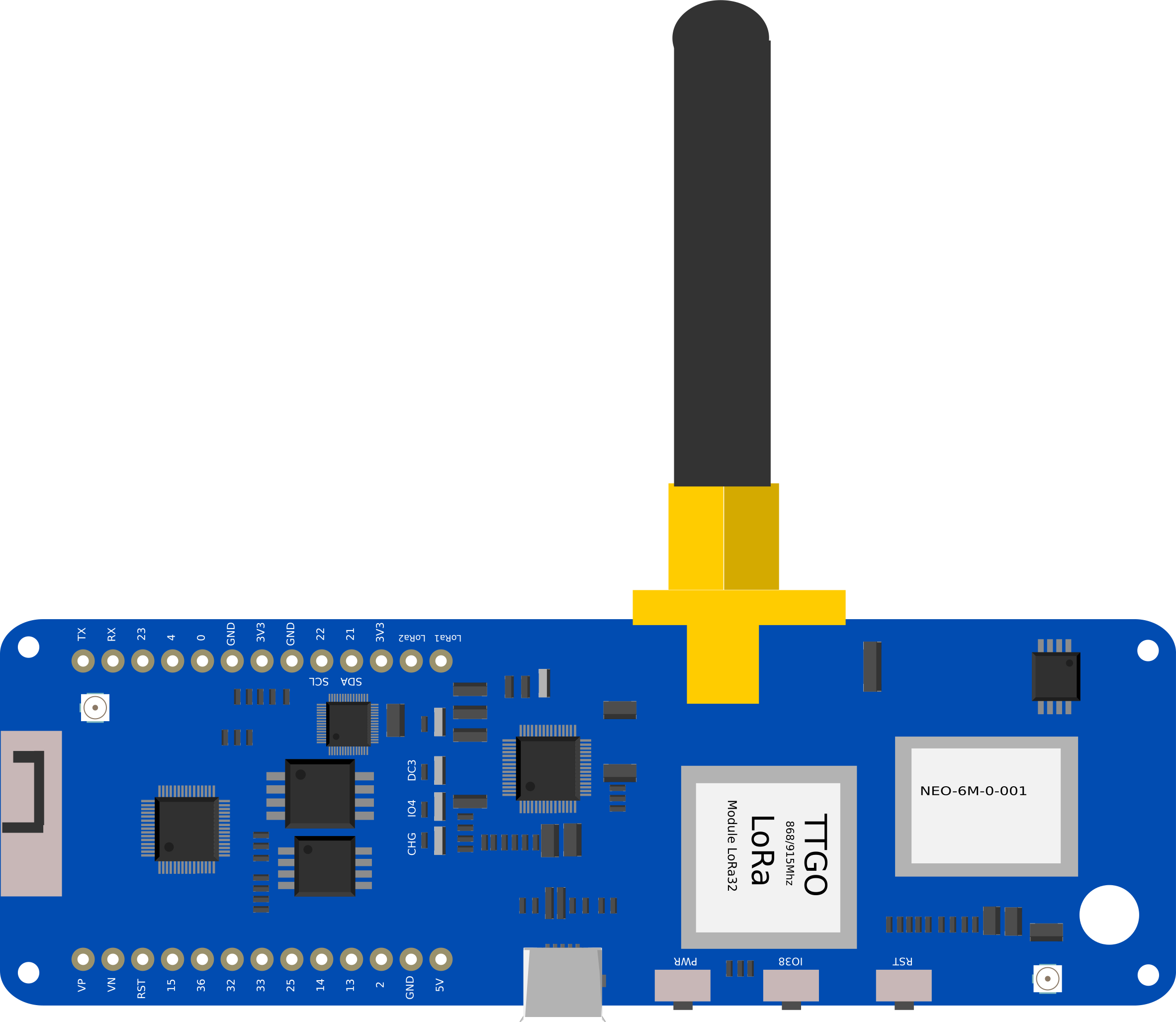
Pin Configuration and Descriptions
| Pin Number | Function | Description |
|---|---|---|
| 1 | 3V3 | 3.3V power supply |
| 2 | GND | Ground |
| 3-6 | GPIO | General Purpose Input/Output |
| 7 | 5V | 5V power supply from USB or battery |
| 8 | TX0 | UART0 transmit |
| 9 | RX0 | UART0 receive |
| 10 | LORA_SCK | LoRa SPI Clock |
| 11 | LORA_MISO | LoRa SPI Master-In Slave-Out |
| 12 | LORA_MOSI | LoRa SPI Master-Out Slave-In |
| 13 | LORA_CS | LoRa Chip Select |
| 14 | LORA_RST | LoRa Reset |
| 15 | LORA_IRQ | LoRa Interrupt Request |
| 16 | GPS_TX | GPS module transmit |
| 17 | GPS_RX | GPS module receive |
Note: This is a simplified pinout for illustration purposes. Refer to the T-Beam datasheet for a complete pinout and description.
Usage Instructions
Integrating T-Beam into a Circuit
- Powering the T-Beam: Connect a 5V power source to the 5V pin or use a LiPo battery.
- Programming the T-Beam: Use the onboard USB port to program the ESP32 with your desired firmware.
- Connecting Peripherals: Utilize the GPIO pins to connect sensors, actuators, or other peripherals as needed.
Important Considerations and Best Practices
- Always ensure that the power supply voltage and current ratings are compatible with the T-Beam specifications.
- When using the LoRa and GPS features, place the T-Beam in a location with a clear view of the sky for optimal signal reception.
- Use proper ESD precautions when handling the T-Beam to prevent damage to the sensitive electronics.
Troubleshooting and FAQs
Common Issues
- GPS Not Locking: Ensure the antenna has a clear view of the sky and that the T-Beam is not inside a building or enclosure that blocks satellite signals.
- LoRa Communication Failure: Check the antenna connections and ensure that there are no obstructions between the transmitting and receiving antennas.
Solutions and Tips
- Power Issues: Verify that the power source is stable and within the recommended voltage range.
- Connectivity Problems: Double-check wiring and solder joints for any loose connections or shorts.
FAQs
Q: Can the T-Beam be used with Arduino IDE?
- A: Yes, the ESP32 microcontroller on the T-Beam is compatible with the Arduino IDE. Make sure to install the appropriate board definitions and drivers.
Q: What is the range of the LoRa communication?
- A: The range can vary from a few kilometers in urban areas up to 10-15 kilometers in open rural areas with clear line of sight.
For more detailed troubleshooting, refer to the T-Beam community forums and support resources.
Example Code for Arduino UNO
Below is an example code snippet for initializing the LoRa module on the T-Beam. This code is intended for use with the Arduino IDE.
#include <SPI.h>
#include <LoRa.h>

// Define the LoRa module pins
#define LORA_SCK 5
#define LORA_MISO 19
#define LORA_MOSI 27
#define LORA_CS 18
#define LORA_RST 14
#define LORA_IRQ 26

void setup() {
  // Initialize serial communication at 9600 baud rate
  Serial.begin(9600);

  // Setup LoRa transceiver module
  LoRa.setPins(LORA_CS, LORA_RST, LORA_IRQ);

  if (!LoRa.begin(915E6)) { // Start LoRa using the frequency 915 MHz
    Serial.println("Starting LoRa failed!");
    while (1);
  }

  Serial.println("LoRa Initializing OK!");
}

void loop() {
  // Code to send and receive LoRa messages goes here
}
Note: The pin numbers in the code are specific to the T-Beam and may differ from other development boards. Always refer to the T-Beam's datasheet for accurate pin mappings.
This documentation provides a basic overview of the T-Beam electronic component. For more detailed information, consult the manufacturer's datasheet and technical resources.