How to Use DC worm gear motor : Examples, Pinouts, and Specs
Introduction
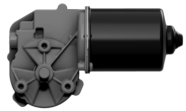
A DC worm gear motor is an electromechanical device that combines a direct current (DC) electric motor with a worm gear transmission. The worm gear mechanism provides a high torque, low-speed output, making this motor ideal for applications that require precise control of movement and a significant reduction in speed from the motor to the driven component. Common applications include automated machinery, robotics, conveyor systems, and accessibility lifts.
Explore Projects Built with DC worm gear motor
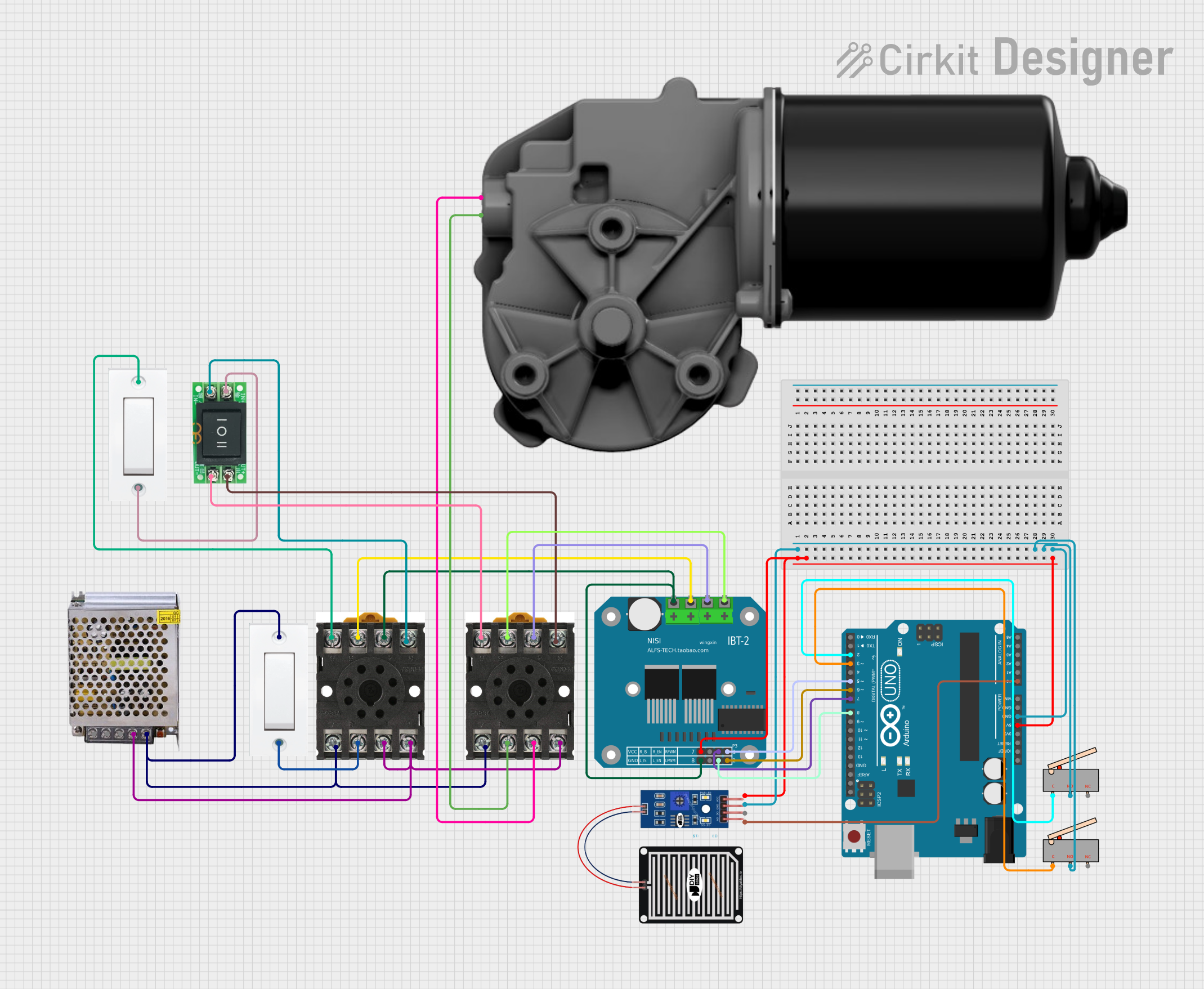

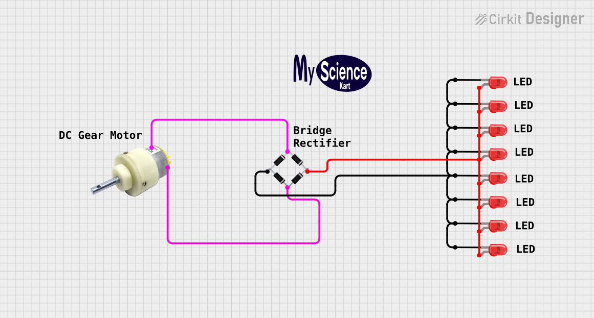
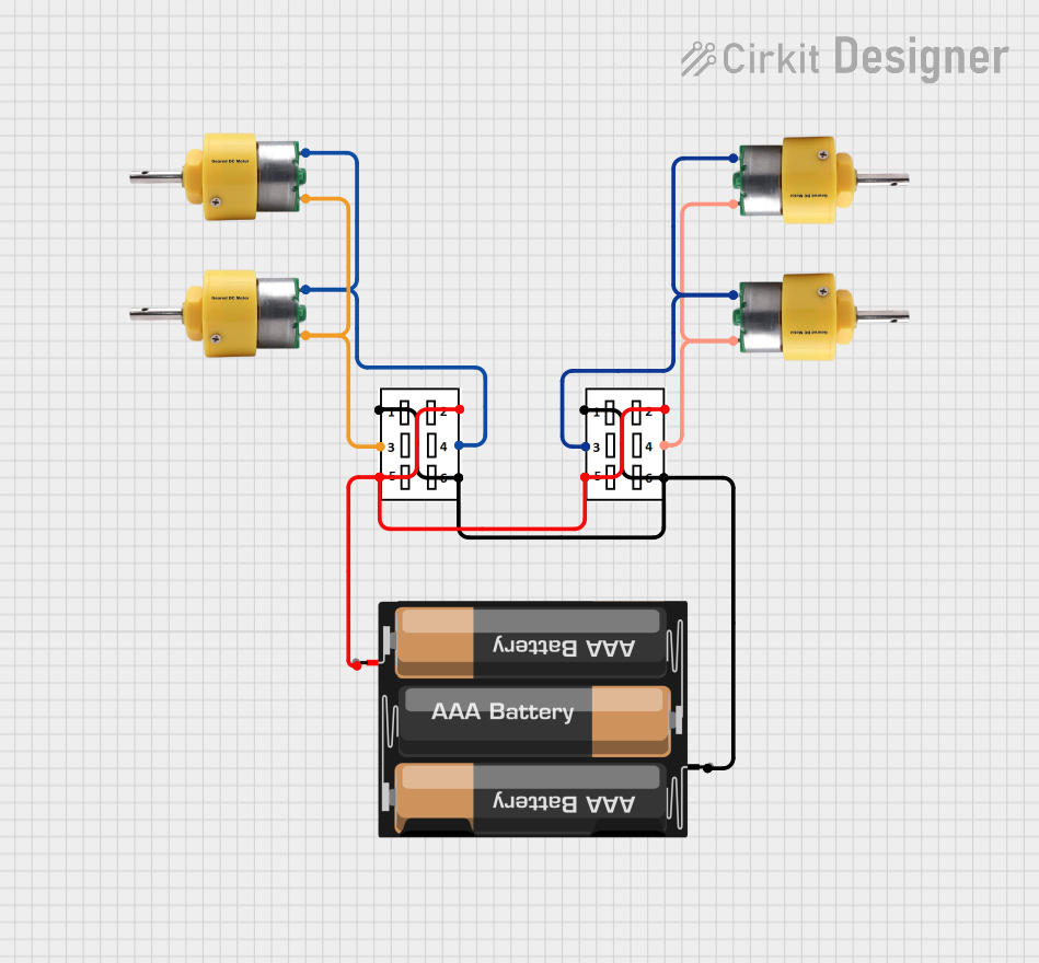
Explore Projects Built with DC worm gear motor
Technical Specifications
General Specifications
| Parameter | Specification | Notes |
|---|---|---|
| Operating Voltage | X - Y VDC | Varies by model |
| No-Load Speed | Z RPM | At rated voltage without load |
| Rated Torque | A Nm | Maximum continuous torque |
| Gear Ratio | B:1 | Reduction from motor to output |
| Efficiency | C% | At rated load |
| Operating Temp. | D - E °C | Safe operating temperature range |
Replace X, Y, Z, A, B, C, D, and E with the specific values for the motor model in question.
Pin Configuration and Descriptions
| Pin Number | Name | Description |
|---|---|---|
| 1 | V+ | Connect to positive voltage supply |
| 2 | GND | Connect to ground |
| 3 | Control 1 | Direction control input (logic level) |
| 4 | Control 2 | Direction control input (logic level) |
Control inputs are optional and may not be present on all models.
Usage Instructions
Wiring the Motor
- Connect the V+ pin to the positive terminal of your DC power supply.
- Connect the GND pin to the ground terminal of your power supply.
- If available, connect the control inputs to your microcontroller or control circuitry to manage the direction of rotation.
Controlling the Motor
- Apply the rated voltage to the motor for optimal performance.
- Use a motor driver or an H-bridge circuit to control the direction and speed.
- Incorporate a current limiting mechanism to protect the motor from overcurrent conditions.
Best Practices
- Ensure the power supply can handle the motor's current draw at startup and under load.
- Use a flyback diode across the motor terminals to protect against voltage spikes.
- Securely mount the motor to prevent vibrations and ensure the alignment of the gear mechanism.
Troubleshooting and FAQs
Common Issues
- Motor not turning: Check power supply connections and voltage levels. Ensure that the control inputs are correctly configured.
- Excessive noise or heat: This may indicate a mechanical issue or overloading. Reduce the load and check for obstructions or misalignment.
- Low torque output: Verify that the motor is operating at the correct voltage and that the gear mechanism is not damaged.
FAQs
Q: Can I reverse the motor's direction?
- A: Yes, by reversing the polarity of the power supply or using the control inputs if available.
Q: What is the lifespan of a DC worm gear motor?
- A: It depends on the usage conditions, but typically these motors are designed for long service life under normal operating conditions.
Q: Can I use PWM to control the motor speed?
- A: Yes, PWM can be used in conjunction with a suitable motor driver to control the speed.
Example Arduino Code
// Example code to control a DC worm gear motor with an Arduino UNO
#include <Arduino.h>

const int motorPin1 = 3; // Control 1 connected to digital pin 3
const int motorPin2 = 4; // Control 2 connected to digital pin 4

void setup() {
  pinMode(motorPin1, OUTPUT);
  pinMode(motorPin2, OUTPUT);
}

void loop() {
  // Rotate motor in one direction
  digitalWrite(motorPin1, HIGH);
  digitalWrite(motorPin2, LOW);
  delay(1000); // Run for 1 second

  // Stop the motor
  digitalWrite(motorPin1, LOW);
  digitalWrite(motorPin2, LOW);
  delay(1000); // Stop for 1 second

  // Rotate motor in the opposite direction
  digitalWrite(motorPin1, LOW);
  digitalWrite(motorPin2, HIGH);
  delay(1000); // Run for 1 second

  // Stop the motor
  digitalWrite(motorPin1, LOW);
  digitalWrite(motorPin2, LOW);
  delay(1000); // Stop for 1 second
}
Note: The above code assumes the use of an H-bridge or motor driver to control the motor. Direct connection of the motor to the Arduino pins without proper driver circuitry can damage the Arduino.
This documentation provides a foundational understanding of the DC worm gear motor and how to integrate it into various applications. Always refer to the specific datasheet of the motor model you are using for precise information and instructions.