How to Use waveshare bus servo driver: Examples, Pinouts, and Specs
Introduction
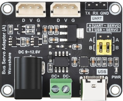
The Waveshare Bus Servo Driver is a specialized driver designed to control multiple servos via a bus interface. It enables precise positioning and movement, making it ideal for robotics, automation, and other applications requiring synchronized servo control. This driver simplifies the process of managing multiple servos by using a single communication bus, reducing wiring complexity and improving scalability.
Explore Projects Built with waveshare bus servo driver
Explore Projects Built with waveshare bus servo driver
Common Applications and Use Cases
- Robotics: Controlling robotic arms, legs, and grippers.
- Automation: Managing servo-driven mechanisms in industrial systems.
- Animatronics: Creating lifelike movements in animatronic models.
- Educational Projects: Teaching servo control and bus communication concepts.
- DIY Projects: Building custom servo-controlled devices.
Technical Specifications
The Waveshare Bus Servo Driver is designed to work seamlessly with a variety of bus servos. Below are its key technical details:
Key Technical Details
- Input Voltage: 6V to 12V DC
- Communication Interface: UART (TTL level)
- Control Protocol: Serial communication with bus servos
- Number of Servos Supported: Up to 253 servos
- Baud Rate: Configurable (default: 115200 bps)
- Dimensions: 65mm x 50mm
- Operating Temperature: -40°C to 85°C
- LED Indicators: Power and communication status
Pin Configuration and Descriptions
The Waveshare Bus Servo Driver features a simple pin layout for easy integration. Below is the pin configuration:
| Pin Name | Description |
|---|---|
| VIN | Power input (6V to 12V DC) |
| GND | Ground |
| TX | UART transmit pin (connect to RX of MCU) |
| RX | UART receive pin (connect to TX of MCU) |
| BUS+ | Positive bus line for servos |
| BUS- | Negative bus line for servos |
Usage Instructions
How to Use the Component in a Circuit
- Power the Driver: Connect a 6V to 12V DC power supply to the VIN and GND pins.
- Connect to a Microcontroller: Use the TX and RX pins to connect the driver to a microcontroller (e.g., Arduino UNO).
- Connect Servos: Attach the bus servos to the BUS+ and BUS- lines. Ensure the servos are compatible with the driver.
- Configure Communication: Set the baud rate on the microcontroller to match the driver's default (115200 bps) or the configured rate.
- Send Commands: Use serial commands to control the servos. Each servo is addressed by its unique ID.
Important Considerations and Best Practices
- Power Supply: Ensure the power supply can handle the total current draw of all connected servos.
- Servo IDs: Assign unique IDs to each servo to avoid communication conflicts.
- Cable Length: Keep the bus cable length as short as possible to minimize signal degradation.
- Termination Resistor: Use a termination resistor at the end of the bus line if communication issues occur.
- Avoid Overloading: Do not exceed the maximum number of servos supported by the driver.
Example Code for Arduino UNO
Below is an example of how to control a servo using the Waveshare Bus Servo Driver and an Arduino UNO:
#include <SoftwareSerial.h>

// Define RX and TX pins for software serial communication
SoftwareSerial mySerial(10, 11); // RX, TX

void setup() {
  // Initialize serial communication with the driver
  mySerial.begin(115200); // Set baud rate to 115200 bps
  Serial.begin(9600);     // For debugging with the Serial Monitor

  // Example: Move servo with ID 1 to position 500
  sendServoCommand(1, 500);
}

void loop() {
  // Add your main code here
}

// Function to send a command to move a servo
void sendServoCommand(uint8_t servoID, uint16_t position) {
  uint8_t command[7];
  command[0] = 0x55; // Header byte 1
  command[1] = 0x55; // Header byte 2
  command[2] = servoID; // Servo ID
  command[3] = 3; // Length of the command
  command[4] = 1; // Command type: Move
  command[5] = position & 0xFF; // Low byte of position
  command[6] = (position >> 8) & 0xFF; // High byte of position

  // Send the command to the driver
  for (int i = 0; i < 7; i++) {
    mySerial.write(command[i]);
  }

  // Debug: Print the command to the Serial Monitor
  Serial.print("Command sent: ");
  for (int i = 0; i < 7; i++) {
    Serial.print(command[i], HEX);
    Serial.print(" ");
  }
  Serial.println();
}
Troubleshooting and FAQs
Common Issues and Solutions
Servos Not Responding
- Cause: Incorrect servo ID or communication settings.
- Solution: Verify the servo ID and ensure the baud rate matches the driver's configuration.
Communication Errors
- Cause: Signal interference or incorrect wiring.
- Solution: Check the wiring, use shorter cables, and add a termination resistor if needed.
Driver Not Powering On
- Cause: Insufficient power supply or loose connections.
- Solution: Ensure the power supply meets the voltage and current requirements, and check all connections.
Servo Jittering
- Cause: Power supply instability or overloaded bus.
- Solution: Use a stable power supply and avoid connecting too many servos.
FAQs
Q: Can I use this driver with standard PWM servos?
A: No, this driver is designed specifically for bus servos that communicate via UART.Q: How do I assign unique IDs to my servos?
A: Refer to the servo's documentation for instructions on setting its ID. Typically, this is done using a configuration tool or specific serial commands.Q: What is the maximum cable length for the bus?
A: The maximum length depends on the environment and cable quality. For best results, keep the cable under 1 meter.Q: Can I daisy-chain multiple drivers?
A: Yes, but ensure each driver has a unique address and sufficient power is supplied to all connected devices.
This documentation provides a comprehensive guide to using the Waveshare Bus Servo Driver effectively. For further assistance, refer to the manufacturer's official resources.