Cirkit Designer Logo
Cirkit Designer
Your all-in-one circuit design IDE
Home / 
Component Documentation

How to Use AS7341 : Examples, Pinouts, and Specs

Image of AS7341
Cirkit Designer LogoDesign with AS7341 in Cirkit Designer

Introduction

The AS7341 is a highly versatile spectral sensor manufactured by Adafruit. It is designed to measure light intensity across multiple wavelengths, making it ideal for applications requiring precise color and light analysis. The sensor features 11 channels for color sensing, including visible and near-infrared light, enabling advanced applications in color recognition, ambient light sensing, and environmental monitoring.

Explore Projects Built with AS7341

Use Cirkit Designer to design, explore, and prototype these projects online. Some projects support real-time simulation. Click "Open Project" to start designing instantly!
Satellite-Based Timing and Navigation System with SDR and Atomic Clock Synchronization
Image of GPS 시스템 측정 구성도_Confirm: A project utilizing AS7341  in a practical application
This circuit appears to be a complex system involving power supply management, GPS and timing synchronization, and data communication. It includes a SI-TEX G1 Satellite Compass for GPS data, an XHTF1021 Atomic Rubidium Clock for precise timing, and Ettus USRP B200 units for software-defined radio communication. Power is supplied through various SMPS units and distributed via terminal blocks and DC jacks. Data communication is facilitated by Beelink MINI S12 N95 computers, RS232 splitters, and a 1000BASE-T Media Converter for network connectivity. RF Directional Couplers are used to interface antennas with the USRP units, and the entire system is likely contained within cases for protection and organization.
Cirkit Designer LogoOpen Project in Cirkit Designer
Battery-Powered Emergency Alert System with NUCLEO-F072RB, SIM800L, and GPS NEO 6M
Image of women safety: A project utilizing AS7341  in a practical application
This circuit is an emergency alert system that uses a NUCLEO-F072RB microcontroller to send SMS alerts and make calls via a SIM800L GSM module, while obtaining location data from a GPS NEO 6M module. The system is powered by a Li-ion battery and includes a TP4056 module for battery charging and protection, with a rocker switch to control power to the microcontroller.
Cirkit Designer LogoOpen Project in Cirkit Designer
Cellular-Enabled IoT Device with Real-Time Clock and Power Management
Image of LRCM PHASE 2 BASIC: A project utilizing AS7341  in a practical application
This circuit features a LilyGo-SIM7000G module for cellular communication and GPS functionality, interfaced with an RTC DS3231 for real-time clock capabilities. It includes voltage sensing through two voltage sensor modules, and uses an 8-channel opto-coupler for isolating different parts of the circuit. Power management is handled by a buck converter connected to a DC power source and batteries, with a fuse for protection and a rocker switch for on/off control. Additionally, there's an LED for indication purposes.
Cirkit Designer LogoOpen Project in Cirkit Designer
Logic Gate Circuit with 7408 AND and 7432 OR ICs
Image of gate: A project utilizing AS7341  in a practical application
This circuit includes a 7408 AND gate IC and a 7432 OR gate IC, both powered by a common VCC and GND connection. The circuit is designed to perform basic logical operations, combining AND and OR gates for digital signal processing.
Cirkit Designer LogoOpen Project in Cirkit Designer

Explore Projects Built with AS7341

Use Cirkit Designer to design, explore, and prototype these projects online. Some projects support real-time simulation. Click "Open Project" to start designing instantly!
Image of GPS 시스템 측정 구성도_Confirm: A project utilizing AS7341  in a practical application
Satellite-Based Timing and Navigation System with SDR and Atomic Clock Synchronization
This circuit appears to be a complex system involving power supply management, GPS and timing synchronization, and data communication. It includes a SI-TEX G1 Satellite Compass for GPS data, an XHTF1021 Atomic Rubidium Clock for precise timing, and Ettus USRP B200 units for software-defined radio communication. Power is supplied through various SMPS units and distributed via terminal blocks and DC jacks. Data communication is facilitated by Beelink MINI S12 N95 computers, RS232 splitters, and a 1000BASE-T Media Converter for network connectivity. RF Directional Couplers are used to interface antennas with the USRP units, and the entire system is likely contained within cases for protection and organization.
Cirkit Designer LogoOpen Project in Cirkit Designer
Image of women safety: A project utilizing AS7341  in a practical application
Battery-Powered Emergency Alert System with NUCLEO-F072RB, SIM800L, and GPS NEO 6M
This circuit is an emergency alert system that uses a NUCLEO-F072RB microcontroller to send SMS alerts and make calls via a SIM800L GSM module, while obtaining location data from a GPS NEO 6M module. The system is powered by a Li-ion battery and includes a TP4056 module for battery charging and protection, with a rocker switch to control power to the microcontroller.
Cirkit Designer LogoOpen Project in Cirkit Designer
Image of LRCM PHASE 2 BASIC: A project utilizing AS7341  in a practical application
Cellular-Enabled IoT Device with Real-Time Clock and Power Management
This circuit features a LilyGo-SIM7000G module for cellular communication and GPS functionality, interfaced with an RTC DS3231 for real-time clock capabilities. It includes voltage sensing through two voltage sensor modules, and uses an 8-channel opto-coupler for isolating different parts of the circuit. Power management is handled by a buck converter connected to a DC power source and batteries, with a fuse for protection and a rocker switch for on/off control. Additionally, there's an LED for indication purposes.
Cirkit Designer LogoOpen Project in Cirkit Designer
Image of gate: A project utilizing AS7341  in a practical application
Logic Gate Circuit with 7408 AND and 7432 OR ICs
This circuit includes a 7408 AND gate IC and a 7432 OR gate IC, both powered by a common VCC and GND connection. The circuit is designed to perform basic logical operations, combining AND and OR gates for digital signal processing.
Cirkit Designer LogoOpen Project in Cirkit Designer

Common Applications

  • Color recognition and matching
  • Ambient light sensing for smart lighting systems
  • Environmental monitoring and analysis
  • Agricultural applications (e.g., plant health monitoring)
  • Industrial quality control and material analysis

Technical Specifications

The AS7341 spectral sensor is packed with advanced features to support a wide range of applications. Below are its key technical specifications:

Parameter Value
Operating Voltage 3.3V (logic level)
Communication Interface I²C
I²C Address (Default) 0x39
Spectral Channels 11 (visible and near-infrared)
Measurement Range 350 nm to 1000 nm
Operating Temperature -40°C to +85°C
Power Consumption Low power mode available
Package Type LGA (Land Grid Array)

Pin Configuration and Descriptions

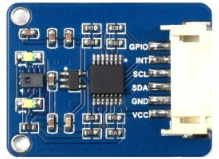
The AS7341 sensor is typically used on a breakout board provided by Adafruit. Below is the pin configuration for the breakout board:

Pin Name Description
VIN Power input (3.3V or 5V)
GND Ground connection
SDA I²C data line
SCL I²C clock line
INT Interrupt pin (optional, for event notifications)
LDR LED driver pin (optional, for external light source)

Usage Instructions

The AS7341 is easy to integrate into projects using its I²C interface. Below are the steps to use the sensor in a circuit and some best practices.

Connecting the AS7341 to an Arduino UNO

  1. Wiring: Connect the AS7341 breakout board to the Arduino UNO as follows:
    • VIN to 5V on the Arduino
    • GND to GND on the Arduino
    • SDA to A4 (I²C data line on Arduino UNO)
    • SCL to A5 (I²C clock line on Arduino UNO)
  2. Install Libraries: Download and install the Adafruit AS7341 library from the Arduino Library Manager.
  3. Upload Code: Use the example code below to read spectral data from the sensor.

Example Code

#include <Wire.h>
#include "Adafruit_AS7341.h"

// Create an instance of the AS7341 sensor
Adafruit_AS7341 as7341;

void setup() {
  Serial.begin(115200); // Initialize serial communication at 115200 baud
  while (!Serial) delay(10); // Wait for the serial monitor to open

  // Initialize I²C communication and the AS7341 sensor
  if (!as7341.begin()) {
    Serial.println("Failed to find AS7341 sensor! Check wiring.");
    while (1) delay(10); // Halt execution if sensor is not found
  }
  Serial.println("AS7341 sensor initialized successfully!");
}

void loop() {
  // Read and print the visible light channels (F1-F6)
  Serial.println("Reading spectral data...");
  Serial.print("Channel F1: "); Serial.println(as7341.readChannel(AS7341_CHANNEL_F1));
  Serial.print("Channel F2: "); Serial.println(as7341.readChannel(AS7341_CHANNEL_F2));
  Serial.print("Channel F3: "); Serial.println(as7341.readChannel(AS7341_CHANNEL_F3));
  Serial.print("Channel F4: "); Serial.println(as7341.readChannel(AS7341_CHANNEL_F4));
  Serial.print("Channel F5: "); Serial.println(as7341.readChannel(AS7341_CHANNEL_F5));
  Serial.print("Channel F6: "); Serial.println(as7341.readChannel(AS7341_CHANNEL_F6));
  
  delay(1000); // Wait 1 second before the next reading
}

Best Practices

  • Use pull-up resistors (typically 4.7kΩ) on the SDA and SCL lines if they are not already included on the breakout board.
  • Ensure the I²C address (default: 0x39) does not conflict with other devices on the same bus.
  • Avoid exposing the sensor to extreme temperatures or humidity to maintain accuracy.
  • Use the INT pin for event-driven applications to reduce power consumption.

Troubleshooting and FAQs

Common Issues

  1. Sensor Not Detected:

    • Cause: Incorrect wiring or I²C address mismatch.
    • Solution: Double-check the connections and ensure the I²C address matches the default (0x39) or the configured address.
  2. Inaccurate Readings:

    • Cause: Ambient light interference or improper calibration.
    • Solution: Shield the sensor from stray light and perform calibration using a known light source.
  3. I²C Communication Errors:

    • Cause: Missing pull-up resistors or incorrect voltage levels.
    • Solution: Add 4.7kΩ pull-up resistors to the SDA and SCL lines if needed. Ensure the logic level matches the microcontroller (3.3V or 5V).

FAQs

  • Can the AS7341 measure UV light?
    No, the AS7341 is designed to measure visible and near-infrared light (350 nm to 1000 nm).

  • What is the purpose of the LDR pin?
    The LDR pin can drive an external LED to provide a controlled light source for measurements.

  • Is the AS7341 compatible with 5V logic?
    Yes, the breakout board includes level shifting, making it compatible with both 3.3V and 5V logic systems.

By following this documentation, you can effectively integrate the AS7341 spectral sensor into your projects and troubleshoot common issues.