How to Use Adafruit LSM6DS33 6-DoF Accel + Gyro IMU: Examples, Pinouts, and Specs
Introduction
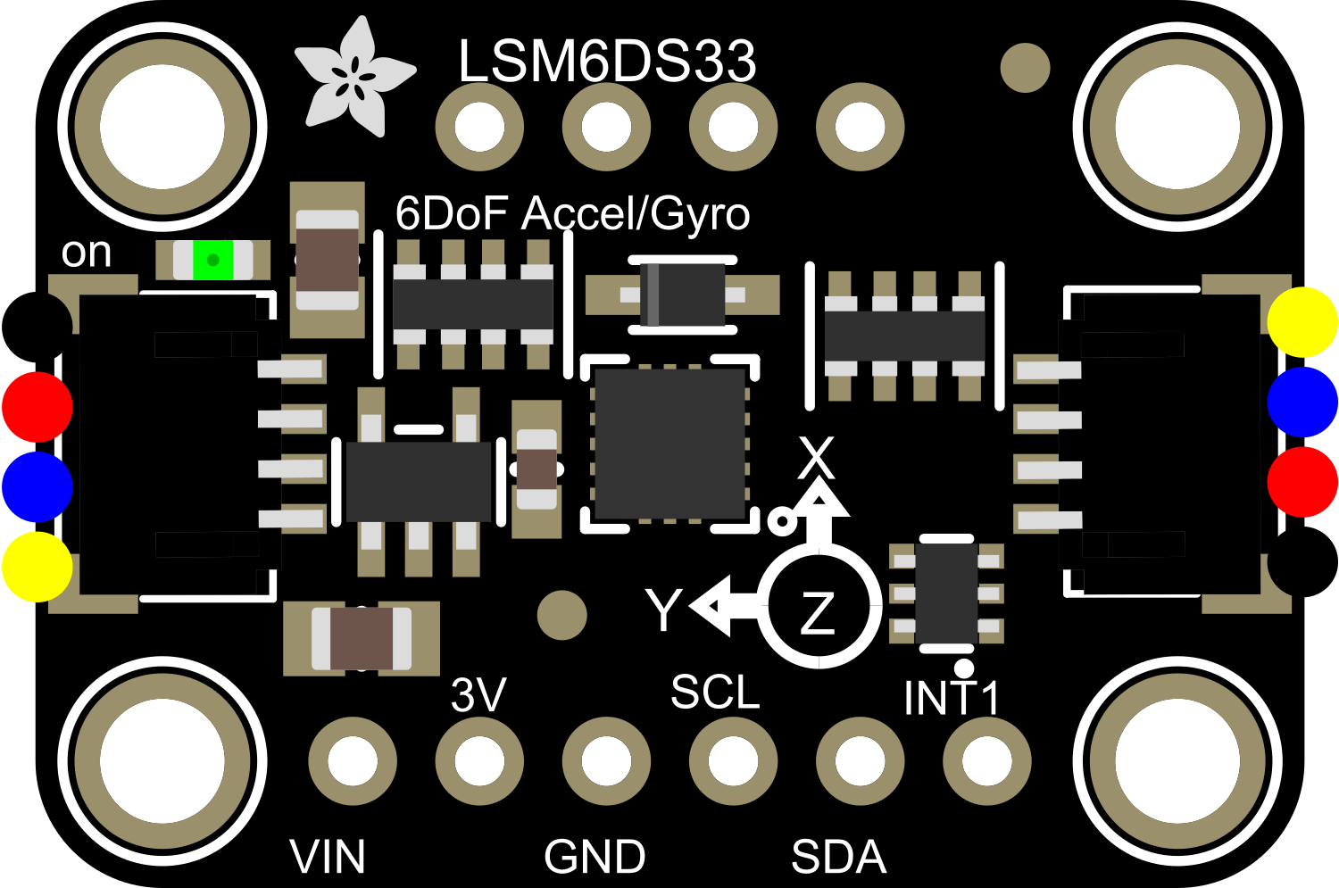
The Adafruit LSM6DS33 is a versatile 6-DoF (Degrees of Freedom) sensor module that combines a digital 3-axis accelerometer and a 3-axis gyroscope. This compact component is designed for motion tracking and orientation sensing in a wide range of applications, from robotics and drones to wearable devices and gaming controllers.
Explore Projects Built with Adafruit LSM6DS33 6-DoF Accel + Gyro IMU
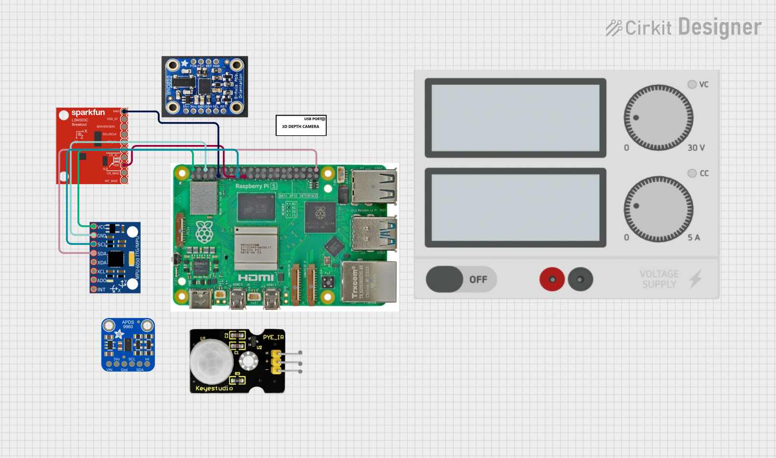


Explore Projects Built with Adafruit LSM6DS33 6-DoF Accel + Gyro IMU
Common Applications and Use Cases
- Motion detection and tracking
- Orientation and tilt sensing
- Gesture recognition
- Robotics and drone stabilization
- Virtual and augmented reality input
- Fitness and health monitoring
Technical Specifications
Key Technical Details
- Accelerometer Range: ±2/±4/±8/±16 g
- Gyroscope Range: ±125/±245/±500/±1000/±2000 dps (degrees per second)
- Supply Voltage: 1.71 V to 3.6 V
- Interface: I2C/SPI
- Operating Temperature Range: -40°C to +85°C
Pin Configuration and Descriptions
| Pin Number | Name | Description |
|---|---|---|
| 1 | VIN | Supply voltage (1.71 V to 3.6 V) |
| 2 | GND | Ground |
| 3 | SCL | I2C clock line / SPI clock line |
| 4 | SDA | I2C data line / SPI data in (SDI) |
| 5 | SDO/SA0 | SPI data out (SDO) / I2C address select |
| 6 | CS | SPI chip select (active low) |
| 7 | INT1 | Interrupt 1 output |
| 8 | INT2 | Interrupt 2 output |
Usage Instructions
How to Use the Component in a Circuit
- Powering the Device: Connect the VIN pin to a 1.71 V to 3.6 V power source and the GND pin to the ground.
- I2C Communication: Connect SCL to the I2C clock line and SDA to the I2C data line on your microcontroller.
- SPI Communication: Connect SCL to SCK, SDA to SDI, SDO/SA0 to SDO, and CS to a digital pin for chip select.
- Address Selection: The SDO/SA0 pin can be used to modify the I2C address if multiple devices are on the same I2C bus.
- Interrupts: The INT1 and INT2 pins can be connected to digital pins on your microcontroller to handle interrupts.
Important Considerations and Best Practices
- Ensure that the power supply is within the specified voltage range to prevent damage.
- Use pull-up resistors on the I2C lines if they are not built into your microcontroller.
- When using SPI, ensure that the CS pin is set to a high state when the device is not in use.
- For accurate readings, calibrate the sensor for zero-g offset and sensitivity.
- Avoid physical shocks and vibrations that exceed the sensor's maximum ratings.
Troubleshooting and FAQs
Common Issues
- No Data Output: Check connections and ensure that the correct communication protocol (I2C/SPI) is selected.
- Inaccurate Readings: Calibrate the sensor, check for nearby magnetic fields, and ensure the sensor is mounted securely.
- Intermittent Communication: Verify pull-up resistors on I2C lines and check for loose connections.
Solutions and Tips for Troubleshooting
- Double-check wiring against the pin configuration table.
- Use example code to test basic functionality before integrating into a larger project.
- Consult the Adafruit LSM6DS33 datasheet for detailed register descriptions and advanced features.
FAQs
Q: Can I use multiple LSM6DS33 sensors on the same I2C bus?
- A: Yes, you can change the I2C address using the SDO/SA0 pin to allow multiple devices on the same bus.
Q: What is the default I2C address?
- A: The default I2C address is 0x6A or 0x6B, depending on the state of the SDO/SA0 pin.
Q: How do I interpret the accelerometer and gyroscope data?
- A: The data from the accelerometer and gyroscope are raw values that need to be converted to meaningful units (g and dps) using the sensor's sensitivity settings.
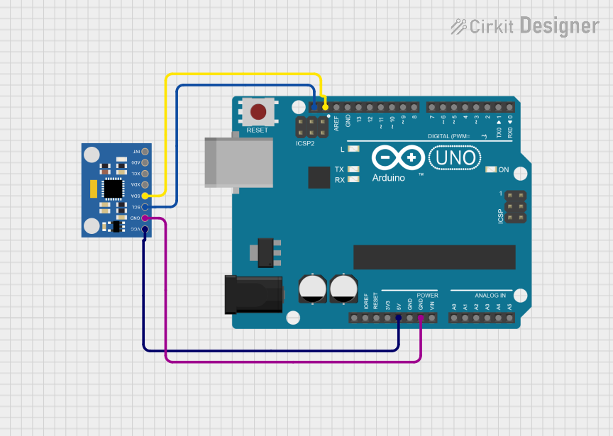
Example Code for Arduino UNO
Below is a simple example code snippet for initializing the LSM6DS33 sensor and reading accelerometer and gyroscope data using an Arduino UNO. This code assumes the use of the Adafruit LSM6DS33 library.
#include <Wire.h>
#include <Adafruit_LSM6DS33.h>

Adafruit_LSM6DS33 lsm6ds33;

void setup() {
  Serial.begin(115200);
  // Initialize the LSM6DS33 sensor
  if (!lsm6ds33.begin_I2C()) {
    Serial.println("Failed to find LSM6DS33 chip");
    while (1) {
      delay(10);
    }
  }
  Serial.println("LSM6DS33 Found!");
}

void loop() {
  // Read accelerometer and gyroscope values
  sensors_event_t accel;
  sensors_event_t gyro;
  sensors_event_t temp;
  lsm6ds33.getEvent(&accel, &gyro, &temp);

  // Print accelerometer data
  Serial.print("Accel X: "); Serial.print(accel.acceleration.x);
  Serial.print(" Y: "); Serial.print(accel.acceleration.y);
  Serial.print(" Z: "); Serial.println(accel.acceleration.z);

  // Print gyroscope data
  Serial.print("Gyro X: "); Serial.print(gyro.gyro.x);
  Serial.print(" Y: "); Serial.print(gyro.gyro.y);
  Serial.print(" Z: "); Serial.println(gyro.gyro.z);

  delay(100);
}
Remember to install the Adafruit LSM6DS33 library through the Arduino Library Manager before uploading this code to your Arduino UNO. This example provides a basic starting point for integrating the LSM6DS33 into your projects.