
How to Use DRIVER MOTOR STEPPE: Examples, Pinouts, and Specs
 Design with DRIVER MOTOR STEPPE in Cirkit Designer
Introduction
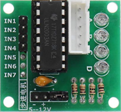
The DRIVER MOTOR STEPPE (ULN2003AN), manufactured by GENJIEHH, is a stepper motor driver designed to control the operation of stepper motors with precision. It achieves this by sending accurate pulses of electricity to the motor, enabling precise positioning and speed control. This component is widely used in applications requiring controlled motion, such as robotics, 3D printers, CNC machines, and automated systems.
The ULN2003AN is a Darlington transistor array that simplifies the process of interfacing stepper motors with microcontrollers or other control systems. It is compatible with a variety of stepper motors, including unipolar stepper motors, and is ideal for projects requiring reliable and efficient motor control.
Explore Projects Built with DRIVER MOTOR STEPPE
 Open Project in Cirkit Designer
 Open Project in Cirkit Designer
 Open Project in Cirkit Designer
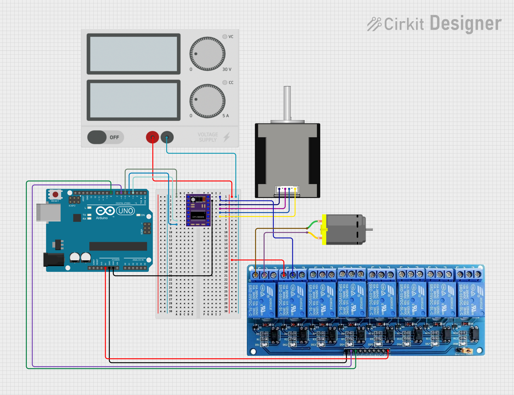 Open Project in Cirkit Designer
Explore Projects Built with DRIVER MOTOR STEPPE
Open Project in Cirkit DesignerOpen Project in Cirkit DesignerOpen Project in Cirkit DesignerOpen Project in Cirkit DesignerTechnical Specifications
Below are the key technical details of the ULN2003AN stepper motor driver:
General Specifications
- Manufacturer: GENJIEHH
- Part ID: ULN2003AN
- Operating Voltage: 5V to 12V (logic input)
- Output Voltage: Up to 50V
- Output Current (per channel): 500mA (maximum)
- Number of Channels: 7 Darlington pairs
- Input Logic Levels: TTL/CMOS compatible
- Package Type: DIP-16 (Dual Inline Package)
- Built-in Protection: Internal freewheeling diodes for inductive load protection
Pin Configuration and Descriptions
The ULN2003AN has 16 pins, as detailed in the table below:
| Pin Number | Pin Name | Description |
|---|---|---|
| 1-7 | Input 1-7 | Logic input pins for controlling the corresponding output channels. |
| 8 | GND | Ground pin. Connect to the ground of the power supply. |
| 9 | COM | Common pin for freewheeling diodes. Connect to the motor power supply (+V). |
| 10-16 | Output 7-1 | Output pins for driving the stepper motor coils or other inductive loads. |
Usage Instructions
How to Use the ULN2003AN in a Circuit
Power Supply:
- Connect the GND (Pin 8) to the ground of your power supply.
- Connect the COM (Pin 9) to the positive terminal of the motor power supply. This enables the internal freewheeling diodes to protect the circuit from voltage spikes caused by inductive loads.
Inputs:
- Connect the Input pins (1-7) to the control signals from your microcontroller or logic circuit. These inputs determine the state of the corresponding output pins.
Outputs:
- Connect the Output pins (10-16) to the stepper motor coils. Ensure the motor's voltage and current ratings are within the ULN2003AN's specifications.
Stepper Motor Control:
- Use a microcontroller (e.g., Arduino UNO) to send control signals to the input pins in the correct sequence to drive the stepper motor.
Important Considerations and Best Practices
- Current Limitation: Ensure the total current drawn by the motor does not exceed the maximum current rating of 500mA per channel. Use external resistors or current-limiting circuits if necessary.
- Heat Dissipation: The ULN2003AN may generate heat during operation. Ensure proper ventilation or use a heatsink if required.
- Freewheeling Diodes: The built-in diodes protect the circuit from voltage spikes. Always connect the COM pin to the motor power supply to enable this protection.
- Logic Levels: Ensure the input logic levels are compatible with the ULN2003AN (TTL/CMOS).
Example Code for Arduino UNO
Below is an example of how to control a unipolar stepper motor using the ULN2003AN and an Arduino UNO:
// Example code to control a stepper motor using ULN2003AN and Arduino UNO

// Define the input pins connected to ULN2003AN
#define IN1 8  // Connect to ULN2003AN Input 1
#define IN2 9  // Connect to ULN2003AN Input 2
#define IN3 10 // Connect to ULN2003AN Input 3
#define IN4 11 // Connect to ULN2003AN Input 4

// Define the step sequence for a unipolar stepper motor
int stepSequence[4][4] = {
  {1, 0, 0, 1}, // Step 1
  {1, 1, 0, 0}, // Step 2
  {0, 1, 1, 0}, // Step 3
  {0, 0, 1, 1}  // Step 4
};

void setup() {
  // Set the input pins as outputs
  pinMode(IN1, OUTPUT);
  pinMode(IN2, OUTPUT);
  pinMode(IN3, OUTPUT);
  pinMode(IN4, OUTPUT);
}

void loop() {
  // Rotate the stepper motor in one direction
  for (int i = 0; i < 4; i++) {
    digitalWrite(IN1, stepSequence[i][0]);
    digitalWrite(IN2, stepSequence[i][1]);
    digitalWrite(IN3, stepSequence[i][2]);
    digitalWrite(IN4, stepSequence[i][3]);
    delay(10); // Adjust delay for speed control
  }
}
Troubleshooting and FAQs
Common Issues and Solutions
Motor Not Moving:
- Cause: Incorrect wiring or missing connections.
- Solution: Double-check all connections, especially the input and output pins. Ensure the motor power supply is connected to the COM pin.
Overheating:
- Cause: Excessive current draw or insufficient ventilation.
- Solution: Verify the motor's current requirements and ensure they are within the ULN2003AN's limits. Add a heatsink or improve ventilation if necessary.
Erratic Motor Movement:
- Cause: Incorrect step sequence or timing.
- Solution: Verify the step sequence in your code and adjust the delay between steps for smoother operation.
Voltage Spikes:
- Cause: COM pin not connected to the motor power supply.
- Solution: Ensure the COM pin is properly connected to the positive terminal of the motor power supply.
FAQs
Can the ULN2003AN drive a bipolar stepper motor?
No, the ULN2003AN is designed for unipolar stepper motors. For bipolar motors, consider using an H-bridge driver like the L298N.What is the maximum motor voltage supported?
The ULN2003AN can handle output voltages up to 50V. Ensure your motor's voltage is within this range.Can I use all 7 channels simultaneously?
Yes, but ensure the total current does not exceed the device's maximum ratings.Is the ULN2003AN compatible with 3.3V logic?
The ULN2003AN is designed for TTL/CMOS logic levels, which typically include 3.3V. However, verify compatibility with your specific microcontroller.