How to Use ESP32 38-pin Expansion Board: Examples, Pinouts, and Specs
Introduction
The ESP32 38-pin Expansion Board, manufactured by Espressif (Part ID: ESP32), is a versatile development platform designed to simplify prototyping and development with the ESP32 microcontroller. This board features 38 pins, providing extensive connectivity options for sensors, modules, and peripherals. It is ideal for IoT applications, smart devices, and rapid prototyping, offering robust performance and flexibility.
Explore Projects Built with ESP32 38-pin Expansion Board

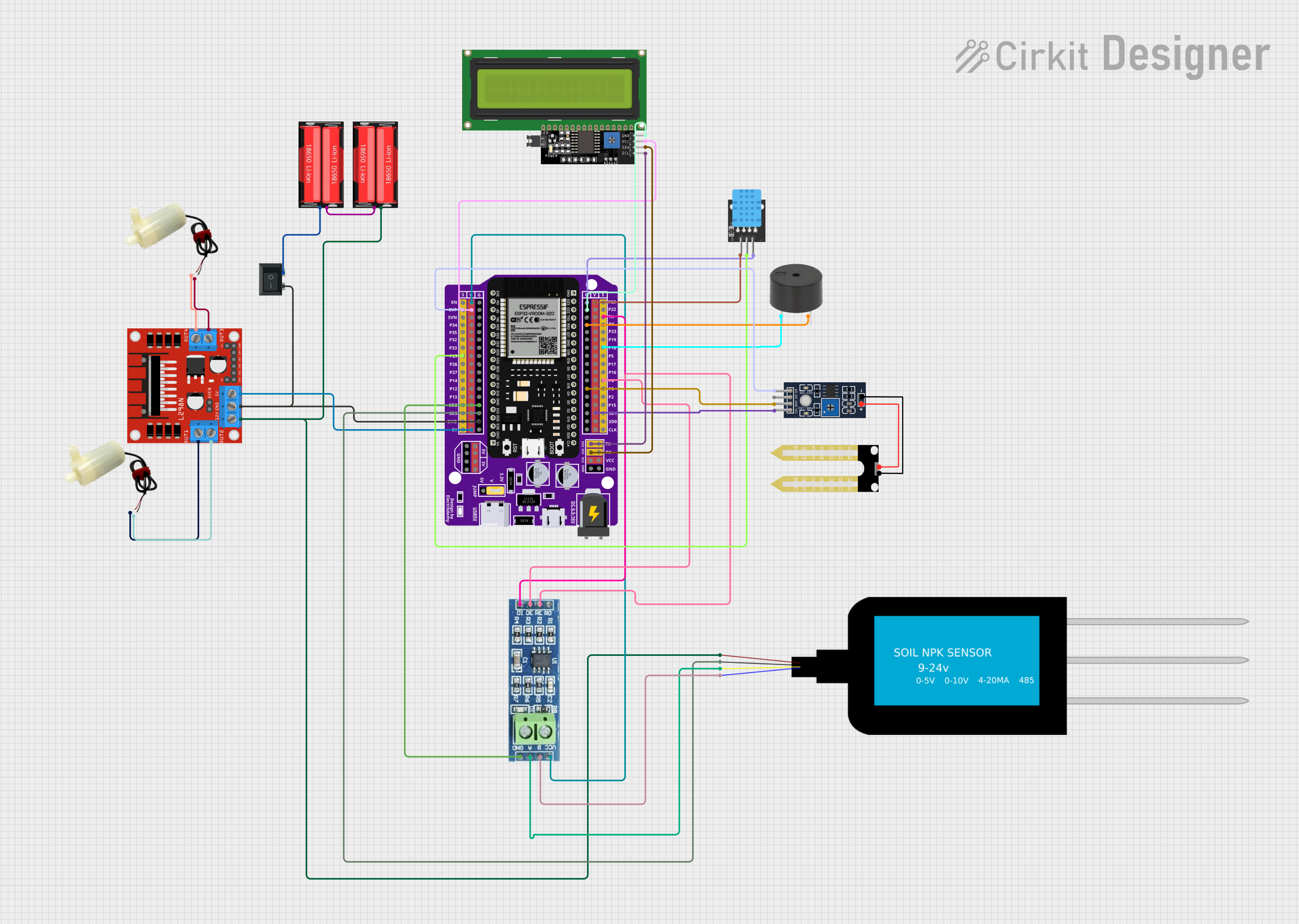
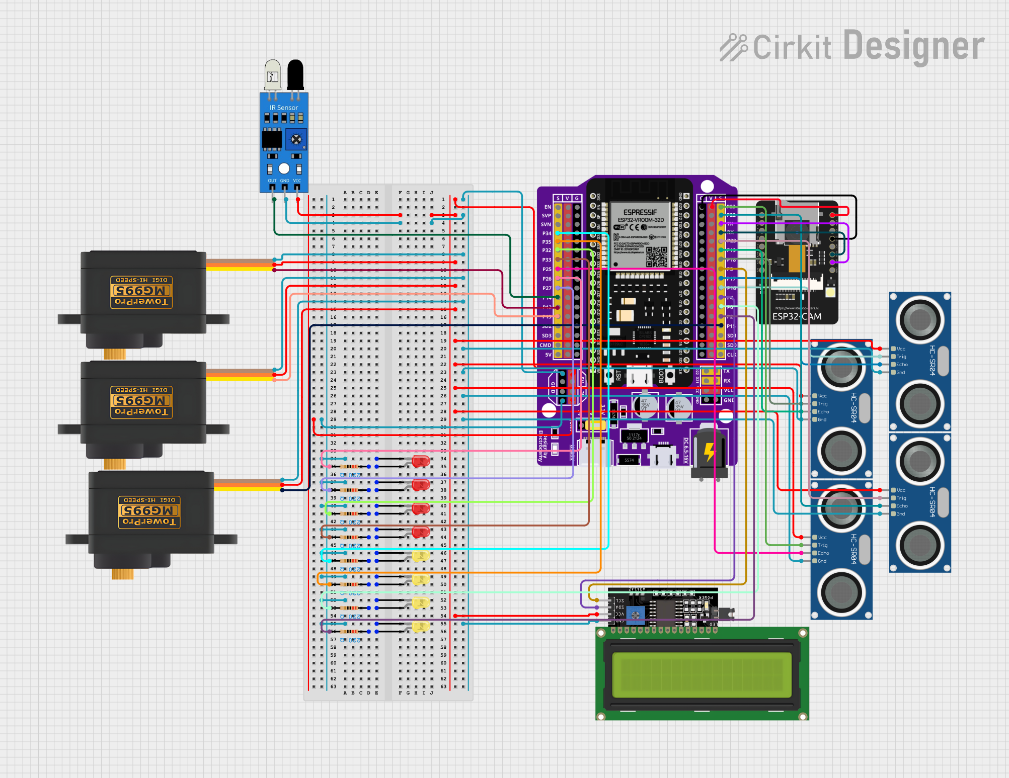

Explore Projects Built with ESP32 38-pin Expansion Board
Common Applications and Use Cases
- IoT Projects: Smart home devices, environmental monitoring, and industrial IoT systems.
- Wearable Technology: Fitness trackers, health monitoring devices, and smart clothing.
- Robotics: Motor control, sensor integration, and autonomous systems.
- Prototyping: Rapid development of proof-of-concept designs.
- Wireless Communication: Wi-Fi and Bluetooth-enabled projects.
Technical Specifications
The ESP32 38-pin Expansion Board is built to support the ESP32 microcontroller, offering a wide range of features and connectivity options.
Key Technical Details
| Parameter | Specification |
|---|---|
| Microcontroller | ESP32 (dual-core Xtensa LX6 processor) |
| Operating Voltage | 3.3V |
| Input Voltage Range | 5V (via USB) or 7-12V (via VIN pin) |
| Digital I/O Pins | 34 |
| Analog Input Pins | 18 (12-bit ADC resolution) |
| PWM Pins | 16 |
| Communication Interfaces | UART, SPI, I2C, I2S |
| Wi-Fi Standard | 802.11 b/g/n |
| Bluetooth Standard | Bluetooth 4.2 + BLE |
| Flash Memory | 4MB (default) |
| Operating Temperature | -40°C to +85°C |
| Dimensions | 57mm x 25mm |
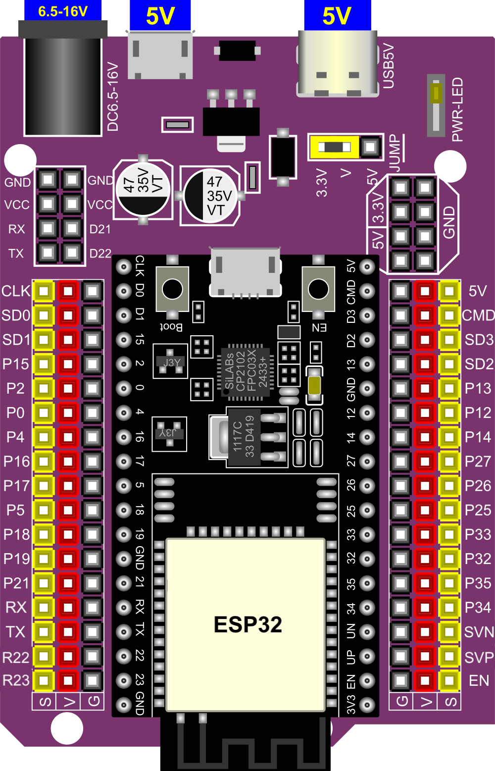
Pin Configuration and Descriptions
The ESP32 38-pin Expansion Board features a 38-pin layout. Below is the pin configuration:
| Pin Name | Type | Description |
|---|---|---|
| VIN | Power Input | External power input (7-12V). |
| 3V3 | Power Output | 3.3V regulated output. |
| GND | Ground | Ground connection. |
| EN | Input | Enable pin to reset the microcontroller. |
| IO0-IO39 | GPIO | General-purpose input/output pins. |
| ADC1/ADC2 | Analog Input | Analog-to-digital converter pins. |
| TXD/RXD | UART | Serial communication pins. |
| SCL/SDA | I2C | I2C clock and data pins. |
| MOSI/MISO/SCK | SPI | SPI communication pins. |
| RST | Reset | Reset pin for the microcontroller. |
Usage Instructions
The ESP32 38-pin Expansion Board is designed for ease of use in a variety of applications. Follow the steps below to integrate it into your project.
How to Use the Component in a Circuit
Powering the Board:
- Connect the board to a computer via a USB cable for 5V power.
- Alternatively, supply 7-12V to the VIN pin for external power.
Connecting Peripherals:
- Use the GPIO pins to connect sensors, actuators, or other modules.
- For analog sensors, connect to the ADC1 or ADC2 pins.
- For communication modules, use UART, SPI, or I2C pins as required.
Programming the ESP32:
- Install the ESP32 board package in the Arduino IDE or use Espressif's ESP-IDF.
- Connect the board to your computer via USB and select the appropriate COM port.
- Write and upload your code to the ESP32.
Important Considerations and Best Practices
- Ensure the input voltage does not exceed the specified range to avoid damaging the board.
- Use level shifters when interfacing with 5V logic devices, as the ESP32 operates at 3.3V.
- Avoid connecting high-current devices directly to GPIO pins; use external drivers or relays.
- Use decoupling capacitors for stable operation when connecting multiple peripherals.
Example Code for Arduino UNO Integration
Below is an example of using the ESP32 38-pin Expansion Board to read data from a DHT11 temperature and humidity sensor:
#include <DHT.h>

// Define the DHT sensor type and pin
#define DHTPIN 4       // GPIO4 is connected to the DHT11 data pin
#define DHTTYPE DHT11  // DHT11 sensor type

DHT dht(DHTPIN, DHTTYPE);

void setup() {
  Serial.begin(115200); // Initialize serial communication
  dht.begin();          // Initialize the DHT sensor
  Serial.println("DHT11 Sensor Test");
}

void loop() {
  delay(2000); // Wait 2 seconds between readings

  // Read temperature and humidity
  float humidity = dht.readHumidity();
  float temperature = dht.readTemperature();

  // Check if readings are valid
  if (isnan(humidity) || isnan(temperature)) {
    Serial.println("Failed to read from DHT sensor!");
    return;
  }

  // Print the results to the Serial Monitor
  Serial.print("Humidity: ");
  Serial.print(humidity);
  Serial.print("%  Temperature: ");
  Serial.print(temperature);
  Serial.println("°C");
}
Troubleshooting and FAQs
Common Issues Users Might Face
Board Not Detected by Computer:
- Ensure the USB cable is functional and supports data transfer.
- Install the correct USB-to-serial driver for the ESP32.
Code Upload Fails:
- Check that the correct COM port and board type are selected in the IDE.
- Press and hold the "BOOT" button on the board while uploading the code.
Peripherals Not Responding:
- Verify the wiring and connections to the GPIO pins.
- Ensure the peripherals are powered and compatible with 3.3V logic.
Wi-Fi or Bluetooth Not Working:
- Check the network credentials in your code.
- Ensure the ESP32 is within range of the Wi-Fi router or Bluetooth device.
Solutions and Tips for Troubleshooting
- Use a multimeter to check voltage levels and continuity in your circuit.
- Test the board with a simple "Blink" sketch to verify basic functionality.
- Refer to the Espressif documentation for advanced debugging techniques.
By following this documentation, you can effectively utilize the ESP32 38-pin Expansion Board for your projects.