How to Use daly bms: Examples, Pinouts, and Specs
Introduction
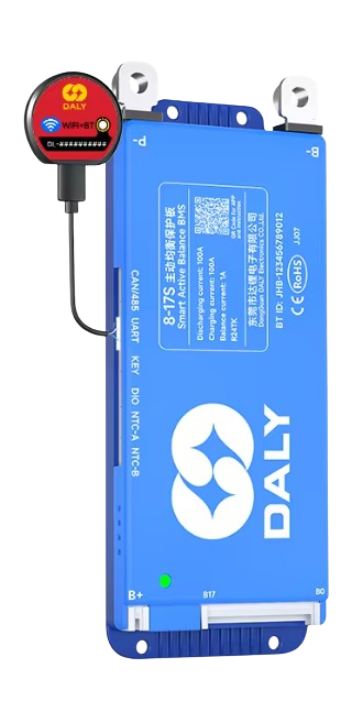
The Daly Battery Management System (BMS) is a sophisticated electronic component designed to monitor and manage battery packs. It ensures the safe operation of batteries by balancing cell voltages and protecting against critical issues such as overcharging, over-discharging, and short circuits. This component is widely used in lithium-ion and lithium iron phosphate (LiFePO4) battery packs, making it an essential tool for applications requiring reliable and efficient energy storage.
Explore Projects Built with daly bms


Explore Projects Built with daly bms
Common Applications and Use Cases
- Electric vehicles (EVs) and e-bikes
- Solar energy storage systems
- Uninterruptible Power Supplies (UPS)
- Portable power stations
- Robotics and industrial equipment
Technical Specifications
The Daly BMS is available in various configurations to support different battery chemistries, voltages, and capacities. Below are the general technical specifications:
Key Technical Details
| Parameter | Specification |
|---|---|
| Supported Battery Types | Lithium-ion, LiFePO4 |
| Voltage Range | 3.2V to 72V (depending on model) |
| Current Ratings | 10A to 500A (model-dependent) |
| Cell Balancing Accuracy | ±10mV |
| Overcharge Protection | Configurable (e.g., 3.65V per cell) |
| Over-discharge Protection | Configurable (e.g., 2.5V per cell) |
| Communication Protocols | UART, RS485, CAN (model-dependent) |
| Operating Temperature | -20°C to 60°C |
| Storage Temperature | -40°C to 80°C |
Pin Configuration and Descriptions
The Daly BMS typically includes a multi-pin connector for interfacing with the battery pack and external systems. Below is a general pinout description:
| Pin Number | Label | Description |
|---|---|---|
| 1 | B+ | Battery pack positive terminal |
| 2 | B- | Battery pack negative terminal |
| 3 | P+ | Load/charger positive terminal |
| 4 | P- | Load/charger negative terminal |
| 5 | C+ | Charger positive terminal (if separate) |
| 6 | C- | Charger negative terminal (if separate) |
| 7 | UART_TX | UART transmit pin for communication |
| 8 | UART_RX | UART receive pin for communication |
| 9 | CAN_H | CAN bus high signal (if supported) |
| 10 | CAN_L | CAN bus low signal (if supported) |
| 11+ | B1, B2, ... | Individual cell connections for voltage sensing |
Note: Pin configurations may vary depending on the specific Daly BMS model. Always refer to the datasheet for your model.
Usage Instructions
How to Use the Daly BMS in a Circuit
Connect the Battery Pack:
- Connect the B+ and B- terminals to the positive and negative terminals of the battery pack, respectively.
- Attach the individual cell connections (B1, B2, etc.) to the corresponding battery cells for voltage monitoring.
Connect the Load and Charger:
- Connect the P+ and P- terminals to the load or charger.
- If the model has separate charging terminals (C+ and C-), use them for the charger.
Enable Communication (Optional):
- Use the UART, RS485, or CAN interface to connect the BMS to a microcontroller, PC, or monitoring system for real-time data and configuration.
Power On:
- Ensure all connections are secure and power on the system. The BMS will automatically begin monitoring and protecting the battery pack.
Important Considerations and Best Practices
- Verify Compatibility: Ensure the Daly BMS model matches your battery chemistry, voltage, and current requirements.
- Secure Connections: Loose or incorrect connections can damage the BMS or battery pack.
- Avoid Overloading: Do not exceed the current rating of the BMS.
- Monitor Temperature: Ensure the BMS operates within its specified temperature range.
- Use Proper Communication Protocols: If using UART, RS485, or CAN, configure the communication settings (e.g., baud rate) as per the datasheet.
Example: Connecting Daly BMS to Arduino UNO
The Daly BMS can communicate with an Arduino UNO via UART. Below is an example code snippet to read data from the BMS:
#include <SoftwareSerial.h>

// Define RX and TX pins for UART communication
SoftwareSerial BMS(10, 11); // RX = pin 10, TX = pin 11

void setup() {
  Serial.begin(9600);       // Initialize Serial Monitor
  BMS.begin(9600);          // Initialize BMS communication at 9600 baud rate
  Serial.println("Daly BMS Communication Initialized");
}

void loop() {
  if (BMS.available()) {
    // Read data from BMS and print to Serial Monitor
    String data = "";
    while (BMS.available()) {
      char c = BMS.read();
      data += c;
    }
    Serial.println("BMS Data: " + data);
  }
  delay(500); // Delay to avoid flooding the Serial Monitor
}
Note: Replace the baud rate with the correct value for your Daly BMS model. Consult the datasheet for communication protocol details.
Troubleshooting and FAQs
Common Issues and Solutions
BMS Not Powering On:
- Cause: Incorrect wiring or insufficient battery voltage.
- Solution: Double-check all connections and ensure the battery pack voltage is within the BMS's operating range.
Overcharge/Over-discharge Protection Triggered:
- Cause: Battery voltage exceeds or drops below the configured thresholds.
- Solution: Verify the battery pack's state of charge and adjust the BMS settings if necessary.
Communication Failure:
- Cause: Incorrect UART, RS485, or CAN settings.
- Solution: Ensure the baud rate and communication protocol match the BMS specifications.
Excessive Heat:
- Cause: Overloading or poor ventilation.
- Solution: Reduce the load or improve airflow around the BMS.
Frequently Asked Questions
Q: Can the Daly BMS be used with other battery chemistries?
A: No, the Daly BMS is designed for specific chemistries like lithium-ion and LiFePO4. Always use a model compatible with your battery type.Q: How do I reset the BMS after a protection event?
A: Disconnect the load and charger, then reconnect them after a few seconds. Some models may require a manual reset.Q: Can I configure the protection thresholds?
A: Yes, many Daly BMS models allow configuration via UART, RS485, or CAN using the manufacturer's software.Q: Is the Daly BMS waterproof?
A: Some models are water-resistant, but not all are fully waterproof. Check the IP rating of your specific model.
By following this documentation, users can effectively integrate and operate the Daly BMS in their battery-powered systems. Always refer to the official datasheet for model-specific details.