Cirkit Designer Logo
Cirkit Designer
Your all-in-one circuit design IDE
Home / 
Component Documentation

How to Use Power Distribution Board: Examples, Pinouts, and Specs

Image of Power Distribution Board
Cirkit Designer LogoDesign with Power Distribution Board in Cirkit Designer

Introduction

A Power Distribution Board (PDB) is an essential component in many electronic systems, particularly in complex circuits and multirotor aircraft. It serves as a hub for distributing electrical power from a single source, such as a battery, to multiple electronic devices or subsystems. PDBs are commonly used in radio-controlled (RC) models, drones, robotics, and other applications where organized power management is crucial.

Explore Projects Built with Power Distribution Board

Use Cirkit Designer to design, explore, and prototype these projects online. Some projects support real-time simulation. Click "Open Project" to start designing instantly!
Multi-Stage Voltage Regulation and Indicator LED Circuit
Image of Subramanyak_Power_Circuit: A project utilizing Power Distribution Board in a practical application
This circuit is designed for power management, featuring buck and boost converters for voltage adjustment, and linear regulators for stable voltage output. It includes LEDs for status indication, and terminal blocks for external connections.
Cirkit Designer LogoOpen Project in Cirkit Designer
Battery-Powered FPV Drone with Telemetry and Dual Motor Control
Image of Krul': A project utilizing Power Distribution Board in a practical application
This circuit appears to be a power distribution and control system for a vehicle with two motorized wheels, possibly a drone or a robot. It includes a lipo battery connected to a Power Distribution Board (PDB) that distributes power to two Electronic Speed Controllers (ESCs) which in turn control the speed and direction of the motors. The system also integrates a flight controller (H743-SLIM V3) for managing various peripherals including GPS, FPV camera system, and a telemetry link (ExpressLRS).
Cirkit Designer LogoOpen Project in Cirkit Designer
Industrial Power Distribution and Safety Control System
Image of Control Diagram: A project utilizing Power Distribution Board in a practical application
This circuit is designed for power distribution and safety control in an industrial setting. It features a main isolator and circuit breaker for power management, multiple PSUs for 5V, 12V, and 24V outputs, and a safety relay system that interfaces with E-stop buttons and a start switch to control a main contactor, ensuring safe operation and emergency power cut-off capabilities.
Cirkit Designer LogoOpen Project in Cirkit Designer
12V Multi-Component Control Circuit
Image of DEWX MOTOR 2: A project utilizing Power Distribution Board in a practical application
This circuit appears to be a power distribution system that supplies power to various components from a 12V 5A power supply. It connects the negative terminal of the power supply to the ground (GND) pins of a mini diaphragm water pump, an RGB LED, a fan, and a water pump, while the positive DC output is connected to the positive pins of the RGB LED and presumably to other components through JST PH 2.0 connectors. The circuit lacks a controlling element, such as a microcontroller, suggesting that the components operate continuously or are switched externally.
Cirkit Designer LogoOpen Project in Cirkit Designer

Explore Projects Built with Power Distribution Board

Use Cirkit Designer to design, explore, and prototype these projects online. Some projects support real-time simulation. Click "Open Project" to start designing instantly!
Image of Subramanyak_Power_Circuit: A project utilizing Power Distribution Board in a practical application
Multi-Stage Voltage Regulation and Indicator LED Circuit
This circuit is designed for power management, featuring buck and boost converters for voltage adjustment, and linear regulators for stable voltage output. It includes LEDs for status indication, and terminal blocks for external connections.
Cirkit Designer LogoOpen Project in Cirkit Designer
Image of Krul': A project utilizing Power Distribution Board in a practical application
Battery-Powered FPV Drone with Telemetry and Dual Motor Control
This circuit appears to be a power distribution and control system for a vehicle with two motorized wheels, possibly a drone or a robot. It includes a lipo battery connected to a Power Distribution Board (PDB) that distributes power to two Electronic Speed Controllers (ESCs) which in turn control the speed and direction of the motors. The system also integrates a flight controller (H743-SLIM V3) for managing various peripherals including GPS, FPV camera system, and a telemetry link (ExpressLRS).
Cirkit Designer LogoOpen Project in Cirkit Designer
Image of Control Diagram: A project utilizing Power Distribution Board in a practical application
Industrial Power Distribution and Safety Control System
This circuit is designed for power distribution and safety control in an industrial setting. It features a main isolator and circuit breaker for power management, multiple PSUs for 5V, 12V, and 24V outputs, and a safety relay system that interfaces with E-stop buttons and a start switch to control a main contactor, ensuring safe operation and emergency power cut-off capabilities.
Cirkit Designer LogoOpen Project in Cirkit Designer
Image of DEWX MOTOR 2: A project utilizing Power Distribution Board in a practical application
12V Multi-Component Control Circuit
This circuit appears to be a power distribution system that supplies power to various components from a 12V 5A power supply. It connects the negative terminal of the power supply to the ground (GND) pins of a mini diaphragm water pump, an RGB LED, a fan, and a water pump, while the positive DC output is connected to the positive pins of the RGB LED and presumably to other components through JST PH 2.0 connectors. The circuit lacks a controlling element, such as a microcontroller, suggesting that the components operate continuously or are switched externally.
Cirkit Designer LogoOpen Project in Cirkit Designer

Common Applications and Use Cases

  • Multirotor drones and RC aircraft for distributing power to motors and electronic speed controllers (ESCs)
  • Robotics for routing power to sensors, actuators, and control units
  • DIY electronics projects requiring multiple power connections
  • Automotive and marine electronics for centralized power management

Technical Specifications

Key Technical Details

  • Input Voltage Range: Typically ranges from 3V to 6S LiPo battery voltage (22.2V)
  • Maximum Current: Varies by model, can range from 20A to 200A or more
  • Power Ratings: Dependent on the specific PDB, with some capable of handling up to 1000W
  • Dimensions: Varies by design, often compact to fit within tight spaces
  • Weight: Lightweight, usually a few grams

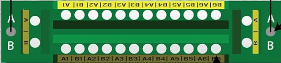
Pin Configuration and Descriptions

Pin Number Description Notes
1 Battery Input (+) Connect to positive battery terminal
2 Battery Input (-) Connect to negative battery terminal
3-n ESC/Motor Outputs (+) Number varies by PDB design
3-n ESC/Motor Outputs (-) Number varies by PDB design
Aux1 Auxiliary Power Output (+) Optional, for accessories
Aux1 Auxiliary Power Output (-) Optional, for accessories

Usage Instructions

How to Use the Component in a Circuit

  1. Connect the Battery:

    • Attach the battery's positive lead to the PDB's positive battery input (Pin 1).
    • Attach the battery's negative lead to the PDB's negative battery input (Pin 2).
  2. Connect the ESCs/Motors:

    • Connect each ESC's positive lead to one of the PDB's positive ESC/Motor outputs.
    • Connect each ESC's negative lead to the corresponding negative ESC/Motor output.
  3. Connect Accessories (if applicable):

    • Attach any additional accessories to the auxiliary power outputs, ensuring correct polarity.

Important Considerations and Best Practices

  • Current Rating: Ensure the PDB's current rating exceeds the total expected current draw of all connected devices.
  • Voltage Rating: Verify that the PDB's voltage rating is suitable for the battery and connected components.
  • Insulation: Use insulating materials to prevent shorts between the PDB and conductive surfaces.
  • Mounting: Secure the PDB to the frame or chassis to prevent movement and potential damage.
  • Wiring: Use appropriately sized wires to handle the expected current and minimize voltage drops.

Troubleshooting and FAQs

Common Issues Users Might Face

  • Overheating: Caused by exceeding the current rating or poor ventilation.
  • Voltage Drops: Occur when wire gauge is too small or connections are loose.
  • Short Circuits: Can happen due to exposed wires or incorrect connections.

Solutions and Tips for Troubleshooting

  • Check Connections: Ensure all connections are secure and correctly polarized.
  • Inspect for Damage: Look for signs of physical damage or burnt components.
  • Measure Voltage and Current: Use a multimeter to verify that the PDB is distributing power correctly.

FAQs

  • Q: Can I use a PDB with a higher voltage rating than my system requires?

    • A: Yes, it's generally safe to use a PDB with a higher voltage rating.
  • Q: What should I do if the PDB is getting too hot during operation?

    • A: Check for overloading and improve ventilation; consider using a PDB with a higher current rating.
  • Q: How do I know if the PDB can handle the current from all my devices?

    • A: Sum the current draw of all connected devices and compare it to the PDB's maximum current rating.

If you're using a PDB with an Arduino UNO or similar microcontroller, the PDB will typically be used to distribute power to various sensors, actuators, or shields that require more current than the Arduino can provide directly. In such cases, no specific code is needed for the PDB itself, as it is a passive component. However, ensure that the power requirements of all connected components are within the specifications of the PDB.