How to Use Modul Buck-Boost 8A: Examples, Pinouts, and Specs
Introduction
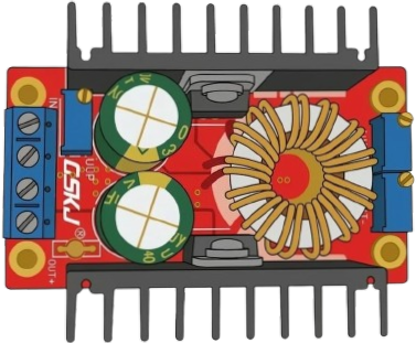
The Modul Buck-Boost 8A by OSKJ is a versatile DC-DC converter module designed to step up or step down voltage levels in electronic circuits. It ensures a stable output voltage even when the input voltage fluctuates, making it ideal for applications requiring consistent power delivery. With a maximum current handling capacity of 8A, this module is suitable for high-power devices and systems.
Explore Projects Built with Modul Buck-Boost 8A


Explore Projects Built with Modul Buck-Boost 8A
Common Applications and Use Cases
- Powering microcontrollers and single-board computers (e.g., Arduino, Raspberry Pi)
- Battery-powered systems requiring voltage regulation
- Solar power systems for voltage stabilization
- LED drivers and lighting systems
- Robotics and motor control circuits
- Portable electronics and power banks
Technical Specifications
The following table outlines the key technical details of the Modul Buck-Boost 8A:
| Parameter | Value |
|---|---|
| Input Voltage Range | 5V to 30V |
| Output Voltage Range | 1.2V to 30V (adjustable) |
| Maximum Output Current | 8A |
| Output Power | Up to 150W |
| Efficiency | Up to 95% (depending on load) |
| Switching Frequency | 150 kHz |
| Operating Temperature | -40°C to +85°C |
| Dimensions | 60mm x 40mm x 20mm |
Pin Configuration and Descriptions
The module has the following input and output connections:
| Pin | Label | Description |
|---|---|---|
| 1 | VIN+ | Positive input voltage terminal |
| 2 | VIN- | Negative input voltage terminal (GND) |
| 3 | VOUT+ | Positive output voltage terminal |
| 4 | VOUT- | Negative output voltage terminal (GND) |
| 5 | ADJ | Voltage adjustment potentiometer (onboard) |
Usage Instructions
How to Use the Modul Buck-Boost 8A in a Circuit
Connect the Input Voltage:
- Attach the positive input voltage to the
VIN+terminal. - Connect the ground (negative) to the
VIN-terminal. - Ensure the input voltage is within the specified range (5V to 30V).
- Attach the positive input voltage to the
Connect the Output Load:
- Attach the positive terminal of your load to
VOUT+. - Connect the ground of your load to
VOUT-.
- Attach the positive terminal of your load to
Adjust the Output Voltage:
- Use the onboard potentiometer labeled
ADJto set the desired output voltage. - Turn the potentiometer clockwise to increase the voltage and counterclockwise to decrease it.
- Use a multimeter to measure the output voltage for precise adjustment.
- Use the onboard potentiometer labeled
Power On:
- Once all connections are secure, power on the module by supplying input voltage.
- Verify the output voltage and current to ensure proper operation.
Important Considerations and Best Practices
- Heat Dissipation: At high currents (close to 8A), the module may generate significant heat. Use a heatsink or active cooling to prevent overheating.
- Input Voltage Range: Ensure the input voltage is always within the specified range to avoid damage to the module.
- Output Voltage Adjustment: Always adjust the output voltage without a load connected to prevent accidental overvoltage to your device.
- Polarity: Double-check the polarity of the input and output connections to avoid damage.
- Current Limitation: Do not exceed the maximum current rating of 8A to ensure safe operation.
Example: Using the Modul Buck-Boost 8A with an Arduino UNO
To power an Arduino UNO with a stable 9V output from a 12V battery, follow these steps:
- Connect the 12V battery's positive terminal to
VIN+and the negative terminal toVIN-. - Adjust the
ADJpotentiometer to set the output voltage to 9V. - Connect
VOUT+to the Arduino's VIN pin andVOUT-to the Arduino's GND pin.
Here is an example Arduino code to blink an LED while powered by the Modul Buck-Boost 8A:
// Simple LED Blink Example
// This code blinks an LED connected to pin 13 of the Arduino UNO.

void setup() {
  pinMode(13, OUTPUT); // Set pin 13 as an output
}

void loop() {
  digitalWrite(13, HIGH); // Turn the LED on
  delay(1000);            // Wait for 1 second
  digitalWrite(13, LOW);  // Turn the LED off
  delay(1000);            // Wait for 1 second
}
Troubleshooting and FAQs
Common Issues and Solutions
No Output Voltage:
- Cause: Incorrect input connections or insufficient input voltage.
- Solution: Verify the polarity and ensure the input voltage is within the 5V to 30V range.
Output Voltage Fluctuates:
- Cause: Load exceeds the module's current capacity or unstable input voltage.
- Solution: Reduce the load or stabilize the input voltage source.
Module Overheats:
- Cause: High current draw or insufficient cooling.
- Solution: Add a heatsink or active cooling, and ensure the current does not exceed 8A.
Cannot Adjust Output Voltage:
- Cause: Faulty potentiometer or incorrect adjustment procedure.
- Solution: Check the potentiometer for damage and adjust it slowly while monitoring the output voltage.
FAQs
Q1: Can I use this module to charge a battery?
A1: Yes, but ensure the output voltage matches the battery's charging voltage, and use a current-limiting circuit if necessary.
Q2: What happens if I reverse the input polarity?
A2: The module does not have reverse polarity protection. Reversing the input polarity may permanently damage the module.
Q3: Can I use this module with a solar panel?
A3: Yes, the module is suitable for solar applications. Ensure the solar panel's output voltage and current are within the module's input range.
Q4: Is the module waterproof?
A4: No, the module is not waterproof. Use it in a dry environment or enclose it in a waterproof case for outdoor use.