How to Use 9DOF Sensor LSM9DS0: Examples, Pinouts, and Specs
Introduction
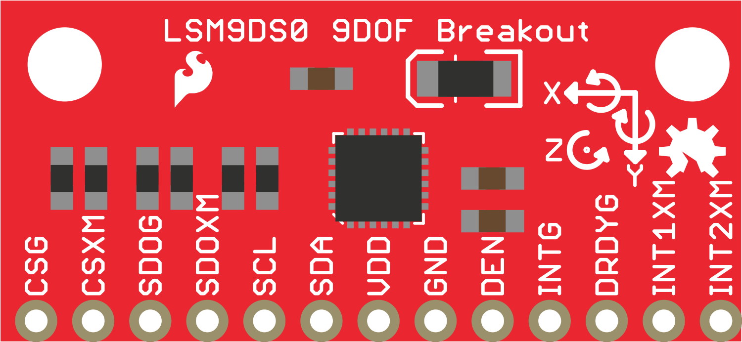
The LSM9DS0 is a versatile 9 Degrees of Freedom (DOF) sensor module that integrates a 3-axis accelerometer, a 3-axis gyroscope, and a 3-axis magnetometer. This sensor is capable of providing precise measurements of motion and orientation, making it an ideal choice for applications in robotics, drones, virtual reality, and other projects requiring motion detection and orientation tracking.
Explore Projects Built with 9DOF Sensor LSM9DS0
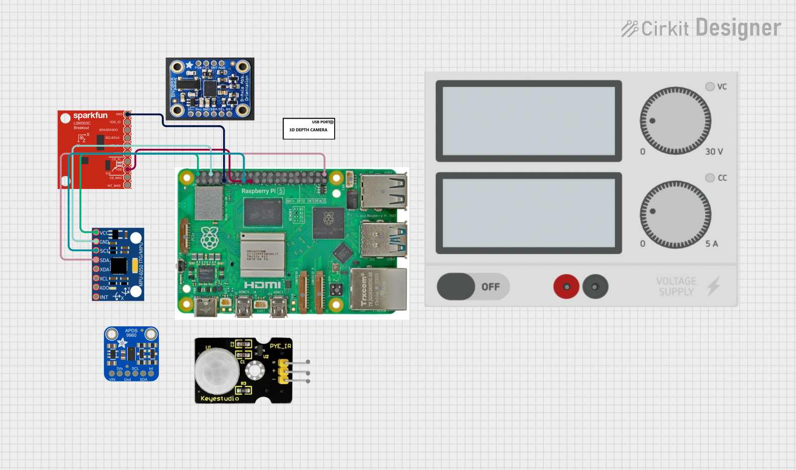


Explore Projects Built with 9DOF Sensor LSM9DS0
Common Applications and Use Cases
- Robotics: For balance control and motion sensing.
- Drones: For flight stabilization and navigation.
- Wearable Devices: For activity tracking and gesture recognition.
- Virtual Reality: For head tracking and immersive experience enhancement.
- Smartphones and Tablets: For screen orientation and motion-based commands.
Technical Specifications
Key Technical Details
- Supply Voltage (VDD): 2.4V to 3.6V
- Operating Current: 10 mA (typical)
- Temperature Range: -40°C to +85°C
- Communication: I2C/SPI serial interface
Pin Configuration and Descriptions
| Pin Number | Pin Name | Description |
|---|---|---|
| 1 | VDD | Power supply voltage (2.4V to 3.6V) |
| 2 | GND | Ground |
| 3 | SCL/SPC | I2C clock / SPI serial clock |
| 4 | SDA/SDI | I2C data / SPI serial data in |
| 5 | SA0/SDO | I2C address selection / SPI serial data out |
| 6 | CS_AG | Accelerometer and gyroscope chip select (active low) |
| 7 | CS_M | Magnetometer chip select (active low) |
| 8 | DRDY_M | Magnetometer data ready output (active high) |
| 9 | DRDY_AG | Accelerometer and gyroscope data ready output (active high) |
| 10 | DEN_AG | Accelerometer and gyroscope data enable (active high) |
Usage Instructions
How to Use the Component in a Circuit
- Power Supply: Connect the VDD pin to a 2.4V to 3.6V power source and the GND pin to ground.
- Data Communication: Choose between I2C or SPI for communication and connect the respective pins to your microcontroller (e.g., Arduino UNO).
- Chip Select: If using SPI, connect CS_AG and CS_M to digital pins on your microcontroller to enable communication with the accelerometer/gyroscope and magnetometer, respectively.
- Data Ready Pins: Optionally, connect DRDY_M and DRDY_AG to digital pins to use the data ready signals.
Important Considerations and Best Practices
- Ensure that the power supply is within the specified voltage range to prevent damage.
- Use pull-up resistors on the I2C lines if they are not already present on the microcontroller board.
- When using SPI, ensure that the CS_AG and CS_M pins are correctly managed to avoid communication conflicts.
- For optimal performance, calibrate the magnetometer in the application environment to account for any magnetic interference.
Example Code for Arduino UNO
#include <Wire.h>
#include <LSM9DS0.h>

LSM9DS0 sensor(Wire, 0x6B, 0x1D);

void setup() {
  Serial.begin(9600);
  sensor.begin();
}

void loop() {
  sensor.readGyro();
  sensor.readAccel();
  sensor.readMag();

  // Print the sensor values
  Serial.print("Gyro (X, Y, Z): ");
  Serial.print(sensor.gx); Serial.print(", ");
  Serial.print(sensor.gy); Serial.print(", ");
  Serial.println(sensor.gz);

  Serial.print("Accel (X, Y, Z): ");
  Serial.print(sensor.ax); Serial.print(", ");
  Serial.print(sensor.ay); Serial.print(", ");
  Serial.println(sensor.az);

  Serial.print("Mag (X, Y, Z): ");
  Serial.print(sensor.mx); Serial.print(", ");
  Serial.print(sensor.my); Serial.print(", ");
  Serial.println(sensor.mz);

  delay(1000); // Update every second
}
Troubleshooting and FAQs
Common Issues Users Might Face
- Inaccurate Readings: Ensure the sensor is calibrated, and there are no magnetic interferences nearby.
- No Data on Serial Monitor: Check the wiring and ensure the correct I2C address or SPI chip select is used.
- Intermittent Communication: Verify the integrity of connections and the presence of necessary pull-up resistors.
Solutions and Tips for Troubleshooting
- Calibration: Perform a calibration routine for the magnetometer to improve accuracy.
- Wiring Check: Double-check all connections, including power supply and ground.
- Code Verification: Ensure that the code uploaded to the microcontroller is correct and that the serial baud rate matches the one set in the Serial Monitor.
FAQs
Q: Can I use the LSM9DS0 with a 5V microcontroller like Arduino UNO? A: Yes, but ensure that the sensor's VDD is connected to a 3.3V output, and use logic level converters for I2C/SPI if necessary.
Q: How do I know if the sensor is functioning correctly? A: Run the example code provided and observe the serial output. If you receive data that changes when you move the sensor, it is functioning correctly.
Q: What is the default I2C address of the LSM9DS0? A: The default I2C address for the accelerometer and gyroscope is 0x6B, and for the magnetometer, it is 0x1D. The SA0/SDO pin can modify these addresses if required.