How to Use 2 speed fan: Examples, Pinouts, and Specs
Introduction
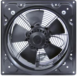
The 2-Speed Fan, manufactured by ESP32 (Part ID: ESP32), is a versatile cooling component designed to operate at two distinct speed settings. This feature allows users to adjust airflow and cooling efficiency based on their specific requirements. The fan is ideal for applications requiring variable cooling, such as electronic enclosures, computer systems, and small appliances. Its compact design and ease of integration make it a popular choice for both hobbyists and professionals.
Explore Projects Built with 2 speed fan


Explore Projects Built with 2 speed fan
Technical Specifications
Below are the key technical details and pin configuration for the 2-Speed Fan:
Key Technical Details
| Parameter | Value |
|---|---|
| Operating Voltage | 5V DC |
| Current Consumption | 0.2A (Low Speed), 0.4A (High Speed) |
| Power Rating | 2W (Low Speed), 4W (High Speed) |
| Speed Settings | Low (50% RPM), High (100% RPM) |
| Dimensions | 40mm x 40mm x 10mm |
| Connector Type | 3-pin (VCC, GND, Speed Control) |
| Operating Temperature | -10°C to 60°C |
| Noise Level | 25 dB (Low Speed), 35 dB (High Speed) |
Pin Configuration
| Pin Name | Description |
|---|---|
| VCC | Power supply input (5V DC) |
| GND | Ground connection |
| Speed Ctrl | Speed control input (Low/High) |
- Speed Control Input: The fan speed is controlled by applying a digital signal to the
Speed Ctrlpin. A LOW signal sets the fan to low speed, while a HIGH signal sets it to high speed.
Usage Instructions
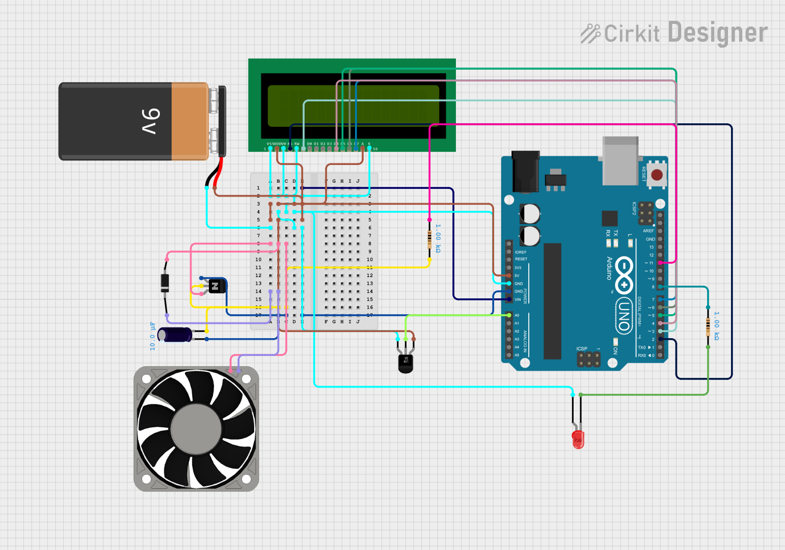
How to Use the 2-Speed Fan in a Circuit
- Power Connection: Connect the
VCCpin to a 5V DC power source and theGNDpin to the ground of your circuit. - Speed Control: Use a microcontroller (e.g., ESP32 or Arduino UNO) to control the fan speed by sending a digital signal to the
Speed Ctrlpin.- Set the
Speed Ctrlpin to LOW for low-speed operation. - Set the
Speed Ctrlpin to HIGH for high-speed operation.
- Set the
Important Considerations and Best Practices
- Ensure the power supply provides a stable 5V DC to avoid damaging the fan.
- Avoid obstructing the fan blades to maintain optimal airflow and prevent motor damage.
- Use a pull-down resistor (e.g., 10kΩ) on the
Speed Ctrlpin to ensure the fan remains off when no signal is applied. - If using an Arduino UNO, connect the
Speed Ctrlpin to a digital output pin capable of providing a 5V signal.
Example Code for Arduino UNO
Below is an example code snippet to control the 2-Speed Fan using an Arduino UNO:
// Define the pin connected to the Speed Ctrl pin of the fan
const int fanSpeedPin = 9;

void setup() {
  // Set the fanSpeedPin as an output
  pinMode(fanSpeedPin, OUTPUT);
}

void loop() {
  // Set fan to low speed
  digitalWrite(fanSpeedPin, LOW);
  delay(5000); // Run at low speed for 5 seconds

  // Set fan to high speed
  digitalWrite(fanSpeedPin, HIGH);
  delay(5000); // Run at high speed for 5 seconds
}
Notes:
- Ensure the
fanSpeedPinis connected to theSpeed Ctrlpin of the fan. - The fan will alternate between low and high speeds every 5 seconds in this example.
Troubleshooting and FAQs
Common Issues and Solutions
Fan Does Not Spin
- Cause: No power supply or incorrect wiring.
- Solution: Verify the
VCCandGNDconnections. Ensure the power supply provides 5V DC.
Fan Stuck at One Speed
- Cause: Faulty or missing signal on the
Speed Ctrlpin. - Solution: Check the connection between the microcontroller and the
Speed Ctrlpin. Ensure the microcontroller is outputting the correct digital signal.
- Cause: Faulty or missing signal on the
Excessive Noise
- Cause: Obstruction in the fan blades or worn-out bearings.
- Solution: Inspect the fan for physical obstructions. If the issue persists, consider replacing the fan.
Fan Overheats
- Cause: Prolonged operation at high speed or insufficient ventilation.
- Solution: Ensure proper ventilation around the fan. Avoid running the fan at high speed continuously for extended periods.
FAQs
Can I use a 3.3V microcontroller to control the fan?
- Yes, but you will need a level shifter or transistor circuit to step up the control signal to 5V.
What happens if I leave the
Speed Ctrlpin unconnected?- The fan will remain off. Use a pull-down resistor to ensure the pin is at a defined LOW state when not driven.
Can I use PWM to control the fan speed?
- No, this fan supports only two fixed speeds (low and high). Use the
Speed Ctrlpin for switching between these speeds.
- No, this fan supports only two fixed speeds (low and high). Use the
Is the fan polarity-protected?
- No, ensure correct polarity when connecting the power supply to avoid damage.