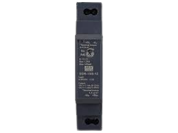
How to Use DDR-15G-12: Examples, Pinouts, and Specs

 Design with DDR-15G-12 in Cirkit Designer
Introduction
The DDR-15G-12 is a high-performance dual-channel data rate (DDR) connector designed for high-speed data transmission in electronic circuits. It is engineered to provide robust connectivity and minimal signal loss, making it ideal for applications where reliable and efficient data transfer is critical.
Explore Projects Built with DDR-15G-12

 Open Project in Cirkit Designer
 Open Project in Cirkit Designer
 Open Project in Cirkit Designer
 Open Project in Cirkit Designer
Explore Projects Built with DDR-15G-12

 Open Project in Cirkit Designer
 Open Project in Cirkit Designer
 Open Project in Cirkit Designer
 Open Project in Cirkit Designer
Common Applications and Use Cases
- High-speed communication systems
- Data acquisition and processing units
- Industrial automation and control systems
- Embedded systems requiring fast data transfer
- Networking equipment and servers
Technical Specifications
Key Technical Details
| Parameter | Value |
|---|---|
| Operating Voltage | 3.3V to 12V |
| Maximum Current Rating | 2A per channel |
| Data Rate | Up to 15 Gbps per channel |
| Operating Temperature | -40°C to +85°C |
| Connector Type | Dual-channel DDR |
| Signal Integrity | Low signal loss, high fidelity |
| Mounting Type | PCB through-hole or surface-mount |
Pin Configuration and Descriptions
The DDR-15G-12 features a dual-channel pin configuration optimized for high-speed data transmission. Below is the pinout description:
| Pin Number | Name | Description |
|---|---|---|
| 1 | VCC | Power supply input (3.3V to 12V) |
| 2 | GND | Ground connection |
| 3 | TX1+ | Positive differential signal for Channel 1 |
| 4 | TX1- | Negative differential signal for Channel 1 |
| 5 | RX1+ | Positive differential signal for Channel 1 |
| 6 | RX1- | Negative differential signal for Channel 1 |
| 7 | TX2+ | Positive differential signal for Channel 2 |
| 8 | TX2- | Negative differential signal for Channel 2 |
| 9 | RX2+ | Positive differential signal for Channel 2 |
| 10 | RX2- | Negative differential signal for Channel 2 |
| 11 | NC | No connection (reserved for future use) |
| 12 | SHIELD | Shielding for EMI protection |
Usage Instructions
How to Use the DDR-15G-12 in a Circuit
- Power Supply: Ensure the power supply voltage is within the range of 3.3V to 12V. Connect the VCC pin to the power source and the GND pin to the ground.
- Signal Connections: Use differential pairs (e.g., TX1+/TX1-, RX1+/RX1-) for transmitting and receiving high-speed data. Maintain proper impedance matching for signal integrity.
- Mounting: Solder the connector onto the PCB using either through-hole or surface-mount techniques, depending on the version of the DDR-15G-12.
- Shielding: Connect the SHIELD pin to the ground plane to minimize electromagnetic interference (EMI).
Important Considerations and Best Practices
- Impedance Matching: Ensure the differential pairs are routed with consistent spacing and controlled impedance to minimize signal reflections.
- Signal Integrity: Use high-quality PCB materials and minimize trace lengths for high-speed signals.
- Thermal Management: Operate the component within the specified temperature range (-40°C to +85°C) to avoid performance degradation.
- Testing: Verify the connections and signal integrity using an oscilloscope or network analyzer before deploying the circuit.
Example: Connecting DDR-15G-12 to an Arduino UNO
While the DDR-15G-12 is not directly compatible with Arduino UNO due to its high-speed data requirements, it can be used in conjunction with external high-speed communication modules. Below is an example of how to interface the DDR-15G-12 with an Arduino UNO for basic power and control:
// Example code for powering the DDR-15G-12 and toggling a control signal
// Note: This example assumes the DDR-15G-12 is used with an external module
// for high-speed data transmission.

#define DDR_POWER_PIN 7  // Pin connected to DDR-15G-12 VCC
#define DDR_GND_PIN   8  // Pin connected to DDR-15G-12 GND

void setup() {
  pinMode(DDR_POWER_PIN, OUTPUT); // Set power pin as output
  pinMode(DDR_GND_PIN, OUTPUT);   // Set ground pin as output

  // Power on the DDR-15G-12
  digitalWrite(DDR_POWER_PIN, HIGH); // Provide power to the DDR-15G-12
  digitalWrite(DDR_GND_PIN, LOW);    // Connect ground
}

void loop() {
  // The DDR-15G-12 operates independently for high-speed data transfer.
  // Add control logic here if needed for external modules.
}
Troubleshooting and FAQs
Common Issues and Solutions
No Data Transmission:
- Cause: Incorrect wiring or power supply issues.
- Solution: Verify all connections, especially the differential pairs (TX+/TX-, RX+/RX-), and ensure the power supply voltage is within the specified range.
Signal Loss or Degradation:
- Cause: Poor PCB layout or impedance mismatch.
- Solution: Use controlled impedance traces and minimize trace lengths for high-speed signals. Ensure proper shielding and grounding.
Overheating:
- Cause: Operating outside the specified temperature range or excessive current draw.
- Solution: Check the operating environment and ensure the current does not exceed 2A per channel.
Electromagnetic Interference (EMI):
- Cause: Inadequate shielding or improper grounding.
- Solution: Connect the SHIELD pin to the ground plane and use proper PCB design practices to minimize EMI.
FAQs
Q1: Can the DDR-15G-12 be used for single-channel applications?
A1: Yes, the DDR-15G-12 can be used for single-channel applications by utilizing only one set of differential pairs (e.g., TX1+/TX1-, RX1+/RX1-).
Q2: Is the DDR-15G-12 compatible with 5V logic levels?
A2: Yes, the DDR-15G-12 supports a wide operating voltage range (3.3V to 12V), making it compatible with 5V logic systems.
Q3: What is the maximum cable length supported?
A3: The maximum cable length depends on the data rate and the quality of the cable. For optimal performance, use high-quality cables and keep lengths as short as possible.
Q4: Can the DDR-15G-12 be used in outdoor environments?
A4: The DDR-15G-12 is designed for industrial-grade applications and can operate in temperatures ranging from -40°C to +85°C. However, additional protection may be required for exposure to moisture or dust.