How to Use LoRa Antenna: Examples, Pinouts, and Specs

Introduction
The Adafruit LoRa Antenna (Part ID: 945) is a high-performance antenna designed specifically for long-range, low-power wireless communication using the LoRa (Long Range) modulation technique. This antenna is an essential component for IoT (Internet of Things) applications, enabling devices to communicate over distances of several kilometers with minimal power consumption. It is compatible with a wide range of LoRa modules and devices, making it a versatile choice for developers and engineers.
Explore Projects Built with LoRa Antenna


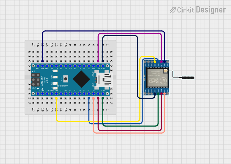
Explore Projects Built with LoRa Antenna
Common Applications and Use Cases
- Smart agriculture (e.g., soil moisture sensors, weather stations)
- Smart cities (e.g., parking sensors, streetlight control)
- Industrial IoT (e.g., asset tracking, predictive maintenance)
- Environmental monitoring (e.g., air quality sensors, water level monitoring)
- Home automation and security systems
Technical Specifications
The Adafruit LoRa Antenna (Part ID: 945) is designed to operate efficiently in the frequency bands used by LoRa communication systems. Below are the key technical details:
General Specifications
| Parameter | Value |
|---|---|
| Frequency Range | 868 MHz / 915 MHz |
| Gain | 2 dBi |
| Impedance | 50 Ω |
| Connector Type | SMA Male |
| Length | 8.6 cm (3.4 inches) |
| Material | Stainless steel and plastic |
| Operating Temperature | -40°C to +85°C |
Pin Configuration and Descriptions
The LoRa antenna does not have traditional pins but connects to a device via an SMA connector. Below is a description of the connector interface:
| Connector Pin | Description |
|---|---|
| Center Pin | Signal (RF transmission and reception) |
| Outer Shell | Ground (shielding and grounding) |
Usage Instructions
How to Use the LoRa Antenna in a Circuit
Connect the Antenna to a LoRa Module:
- Ensure the LoRa module has an SMA female connector.
- Screw the Adafruit LoRa Antenna (Part ID: 945) onto the SMA connector of the module. Tighten gently to avoid damaging the threads.
Verify Frequency Compatibility:
- Confirm that the LoRa module operates in the same frequency band as the antenna (868 MHz or 915 MHz).
Position the Antenna:
- Place the antenna in a vertical orientation for optimal signal strength.
- Avoid placing the antenna near metal objects or inside enclosures that may block RF signals.
Power On the System:
- Once the antenna is securely connected, power on the LoRa module and begin communication.
Important Considerations and Best Practices
- Avoid Operating Without an Antenna: Running a LoRa module without an antenna can damage the RF circuitry.
- Use a Matching Frequency: Ensure the antenna frequency matches the operating frequency of your LoRa module.
- Minimize Interference: Keep the antenna away from sources of electromagnetic interference (e.g., motors, power supplies).
- Check Connector Compatibility: Verify that the SMA connector type (male/female) matches your LoRa module.
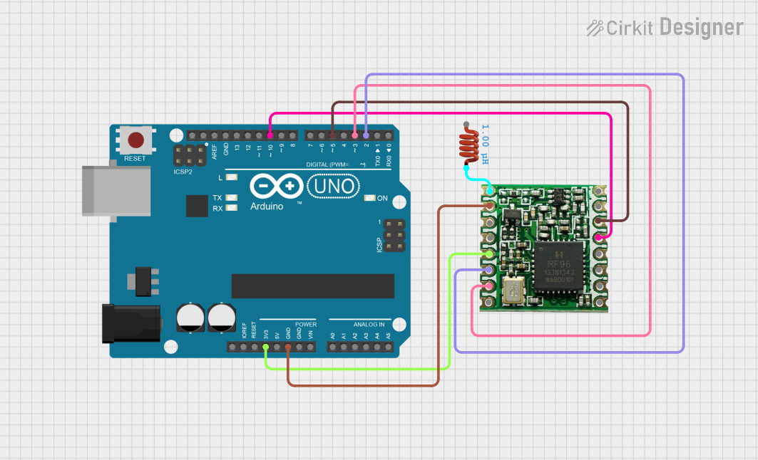
Example: Using the LoRa Antenna with an Arduino UNO
To use the Adafruit LoRa Antenna with an Arduino UNO, you will need a LoRa module (e.g., RFM95) that supports SMA connectors. Below is an example code snippet for sending a simple LoRa message:
#include <SPI.h>
#include <LoRa.h>

// Define LoRa module pins
#define LORA_SS 10    // LoRa module's chip select pin
#define LORA_RST 9    // LoRa module's reset pin
#define LORA_DIO0 2   // LoRa module's DIO0 pin

void setup() {
  Serial.begin(9600); // Initialize serial communication
  while (!Serial);

  Serial.println("LoRa Sender");

  // Initialize LoRa module
  LoRa.setPins(LORA_SS, LORA_RST, LORA_DIO0);
  if (!LoRa.begin(915E6)) { // Set frequency to 915 MHz
    Serial.println("Starting LoRa failed!");
    while (1);
  }
  Serial.println("LoRa initialized successfully.");
}

void loop() {
  Serial.println("Sending packet...");
  LoRa.beginPacket();          // Start a new LoRa packet
  LoRa.print("Hello, LoRa!");  // Add message to the packet
  LoRa.endPacket();            // Send the packet
  delay(5000);                 // Wait 5 seconds before sending again
}
Notes:
- Replace
915E6with868E6if using the 868 MHz frequency band. - Ensure the LoRa module is properly connected to the Arduino UNO.
Troubleshooting and FAQs
Common Issues and Solutions
| Issue | Solution |
|---|---|
| Weak or no signal reception | Ensure the antenna is securely connected and positioned vertically. |
| Mismatched frequency error | Verify that the antenna and LoRa module operate on the same frequency. |
| Damaged SMA connector | Inspect the connector for physical damage and replace if necessary. |
| Interference from nearby devices | Move the antenna away from sources of electromagnetic interference. |
| LoRa module overheating | Do not operate the module without an antenna to prevent RF damage. |
FAQs
Can I use this antenna with any LoRa module?
- Yes, as long as the module has an SMA female connector and operates at 868 MHz or 915 MHz.
What is the maximum range of this antenna?
- The range depends on environmental factors, but it can typically achieve several kilometers in open areas.
Can I use this antenna indoors?
- Yes, but the range may be reduced due to walls and other obstructions.
Is this antenna waterproof?
- The antenna is weather-resistant but not fully waterproof. Use additional protection for outdoor installations.
By following this documentation, you can effectively integrate the Adafruit LoRa Antenna (Part ID: 945) into your IoT projects and achieve reliable long-range communication.