
How to Use Adafruit bq25185 with 3.3V Output: Examples, Pinouts, and Specs
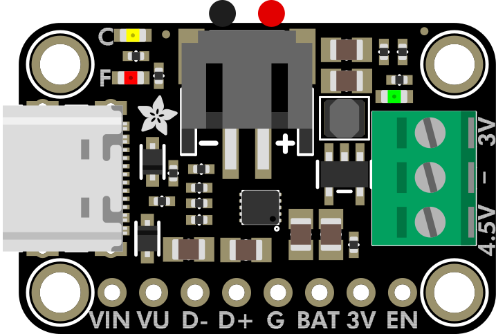
 Design with Adafruit bq25185 with 3.3V Output in Cirkit Designer
Introduction
The Adafruit bq25185 (Manufacturer Part ID: 6092) is a highly integrated battery management IC designed for charging and power management of lithium-ion batteries. It features a regulated 3.3V output, making it ideal for powering microcontrollers, sensors, and other low-power devices. This component is compact, efficient, and versatile, making it a popular choice for portable and battery-powered applications.
Explore Projects Built with Adafruit bq25185 with 3.3V Output
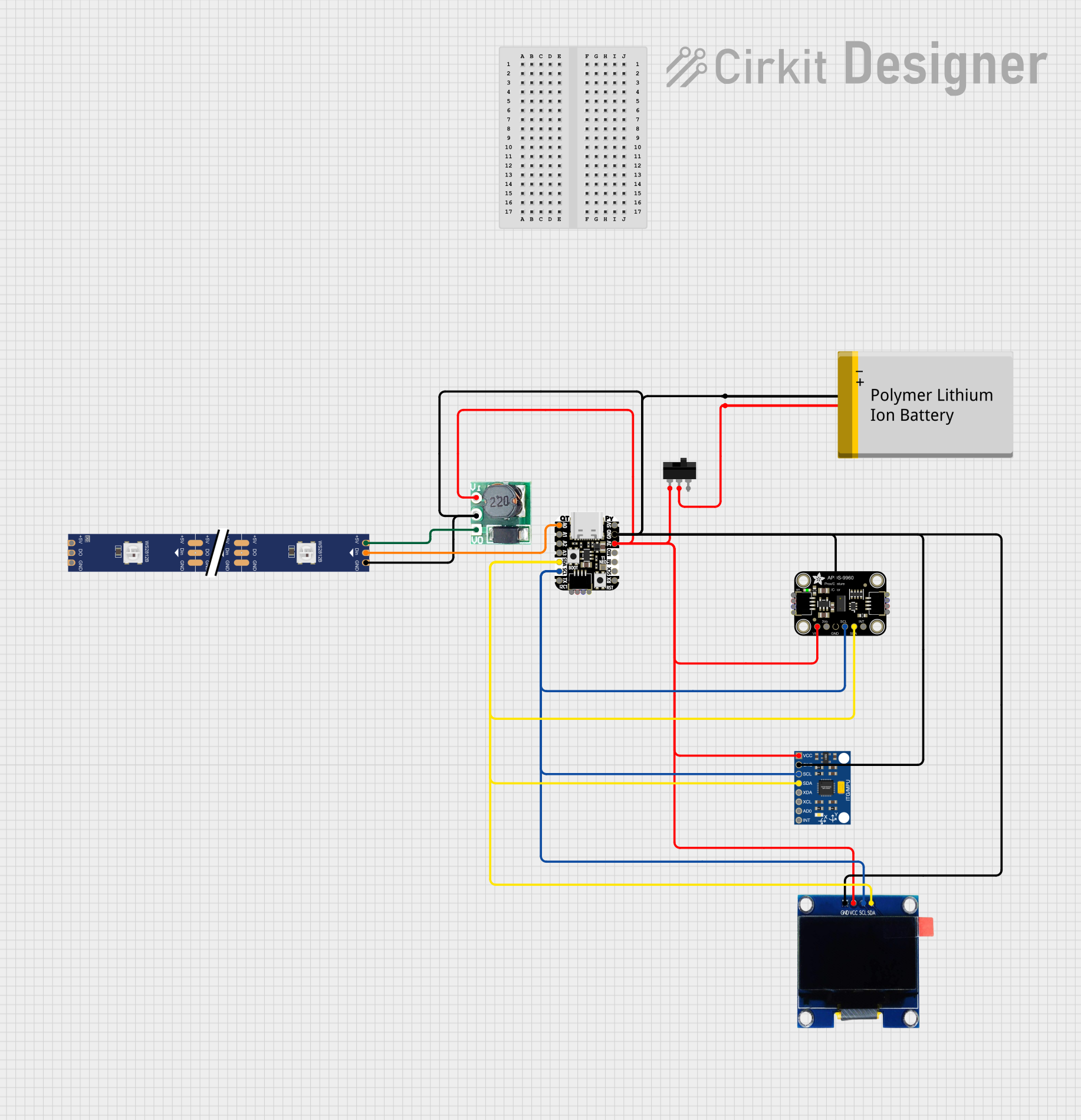 Open Project in Cirkit Designer
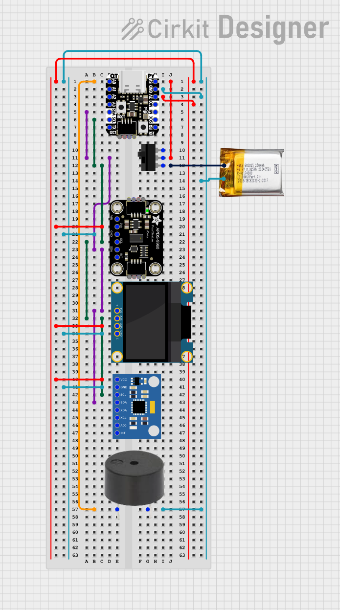 Open Project in Cirkit Designer
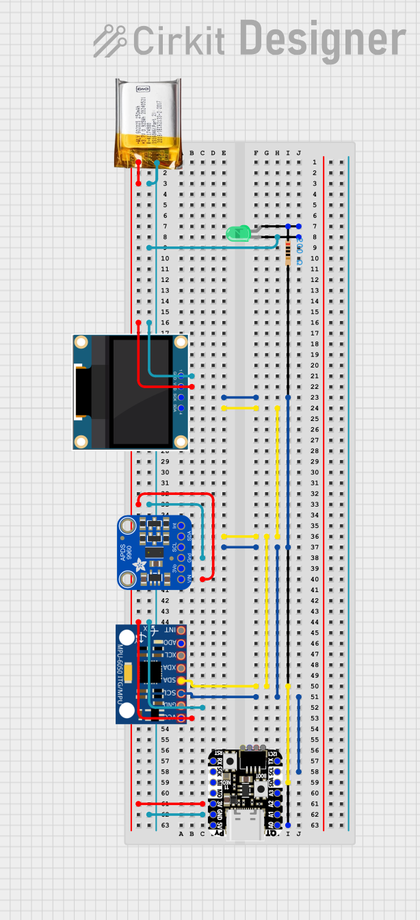 Open Project in Cirkit Designer
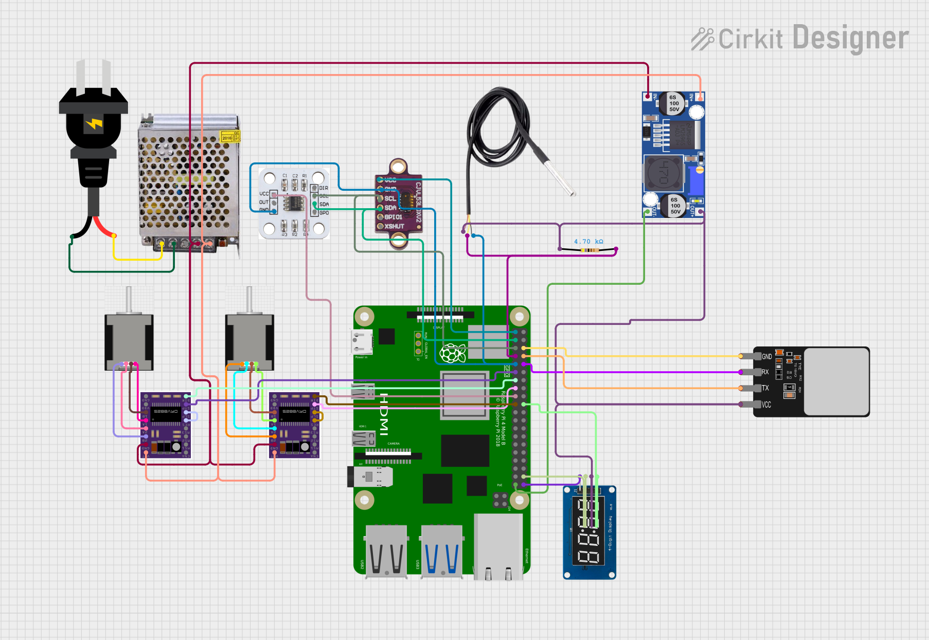 Open Project in Cirkit Designer
Explore Projects Built with Adafruit bq25185 with 3.3V Output
Open Project in Cirkit DesignerOpen Project in Cirkit DesignerOpen Project in Cirkit DesignerOpen Project in Cirkit DesignerCommon Applications
- Wearable devices
- IoT (Internet of Things) projects
- Portable electronics
- Low-power microcontroller-based systems
- Battery-powered sensors and modules
Technical Specifications
The Adafruit bq25185 is packed with features to simplify battery management and power regulation. Below are its key technical specifications:
Key Features
- Input Voltage Range: 3.5V to 6.5V
- Battery Charging Voltage: Configurable up to 4.2V
- Output Voltage: 3.3V regulated
- Maximum Charging Current: 500mA
- Quiescent Current: Ultra-low, ~700nA in ship mode
- Battery Chemistry: Lithium-ion or lithium-polymer
- Protection Features: Overvoltage, undervoltage, overcurrent, and thermal protection
- Package Type: QFN (Quad Flat No-lead)
Pin Configuration and Descriptions
The bq25185 IC is mounted on an Adafruit breakout board for ease of use. Below is the pinout for the breakout board:
| Pin Name | Type | Description |
|---|---|---|
| VIN | Power Input | Input voltage (3.5V to 6.5V) for charging the battery and powering the system. |
| GND | Ground | Ground connection for the circuit. |
| BAT | Power Input | Connect to the positive terminal of the lithium-ion battery. |
| 3V3 | Power Output | Regulated 3.3V output for powering external devices. |
| EN | Digital Input | Enable pin. Pull high to enable the 3.3V output. |
| STAT | Digital Output | Status indicator for charging (low = charging, high = charge complete). |
| I2C SDA | Digital I/O | I2C data line for communication with a microcontroller. |
| I2C SCL | Digital I/O | I2C clock line for communication with a microcontroller. |
| TS | Analog Input | Temperature sensor input for battery monitoring. |
| INT | Digital Output | Interrupt pin for signaling events like faults or status changes. |
Usage Instructions
The Adafruit bq25185 is straightforward to use in a variety of applications. Below are the steps and best practices for integrating it into your project.
Basic Circuit Setup
- Power Input: Connect a 3.5V to 6.5V power source to the
VINpin. This can be a USB power supply or a DC adapter. - Battery Connection: Attach the positive terminal of a lithium-ion battery to the
BATpin and the negative terminal toGND. - 3.3V Output: Use the
3V3pin to power your microcontroller or other low-power devices. Ensure theENpin is pulled high to enable the output. - I2C Communication: If you need to configure or monitor the IC, connect the
SDAandSCLpins to your microcontroller's I2C bus.
Important Considerations
- Battery Protection: Ensure the battery has built-in protection circuitry or use an external protection circuit.
- Thermal Management: Avoid placing the IC near heat sources, as excessive heat can affect performance.
- Enable Pin: The
ENpin must be pulled high to activate the 3.3V output. Use a pull-up resistor if necessary. - I2C Address: The default I2C address for the bq25185 is
0x6B. Ensure no other devices on the bus share this address.
Example: Using with Arduino UNO
The following example demonstrates how to read the charging status of the bq25185 using an Arduino UNO via I2C.
#include <Wire.h>

// Define the I2C address of the bq25185
#define BQ25185_I2C_ADDRESS 0x6B

void setup() {
  Wire.begin(); // Initialize I2C communication
  Serial.begin(9600); // Start serial communication for debugging

  // Check communication with the bq25185
  Wire.beginTransmission(BQ25185_I2C_ADDRESS);
  if (Wire.endTransmission() == 0) {
    Serial.println("bq25185 detected!");
  } else {
    Serial.println("Error: bq25185 not detected. Check connections.");
  }
}

void loop() {
  // Read the status register (example: register 0x0B)
  Wire.beginTransmission(BQ25185_I2C_ADDRESS);
  Wire.write(0x0B); // Address of the status register
  Wire.endTransmission(false); // Send repeated start
  Wire.requestFrom(BQ25185_I2C_ADDRESS, 1); // Request 1 byte of data

  if (Wire.available()) {
    uint8_t status = Wire.read();
    Serial.print("Charging Status: ");
    if (status & 0x01) {
      Serial.println("Charging");
    } else {
      Serial.println("Not Charging");
    }
  }

  delay(1000); // Wait 1 second before reading again
}
Notes on the Code
- The example reads the charging status from the bq25185's status register.
- Ensure proper pull-up resistors (typically 4.7kΩ) are connected to the
SDAandSCLlines.
Troubleshooting and FAQs
Common Issues
No Output on 3V3 Pin
- Ensure the
ENpin is pulled high. - Verify the input voltage on the
VINpin is within the specified range (3.5V to 6.5V). - Check the battery connection to the
BATpin.
- Ensure the
I2C Communication Fails
- Confirm the I2C address (
0x6B) matches the one in your code. - Check the
SDAandSCLconnections and ensure pull-up resistors are present. - Verify the microcontroller's I2C pins are correctly configured.
- Confirm the I2C address (
Overheating
- Ensure the IC is not exposed to excessive ambient temperatures.
- Check for short circuits or excessive current draw on the
3V3output.
FAQs
Q: Can I use the bq25185 without a battery?
A: Yes, the bq25185 can operate without a battery connected. However, ensure the input voltage on VIN is stable and within the specified range.
Q: What happens if the battery is over-discharged?
A: The bq25185 includes undervoltage protection to prevent damage to the battery. It will stop drawing power from the battery if the voltage drops below a safe threshold.
Q: Can I adjust the charging current?
A: Yes, the charging current can be configured via I2C. Refer to the bq25185 datasheet for details on programming the current settings.
Q: Is the 3.3V output always active?
A: No, the 3.3V output is only active when the EN pin is pulled high. Ensure this pin is properly configured in your circuit.
This concludes the documentation for the Adafruit bq25185 with 3.3V Output. For further details, refer to the official datasheet or Adafruit's product page.