How to Use 5V Relay Module: Examples, Pinouts, and Specs
Introduction
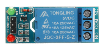
The 5V Relay Module is an electronic switch that enables a low-voltage control signal to control a higher voltage circuit. It is widely used in applications where electrical isolation and high-power switching are required. The module typically consists of a relay (an electromechanical switch) and additional circuitry to interface with microcontrollers or other control systems.
Explore Projects Built with 5V Relay Module


Explore Projects Built with 5V Relay Module
Common Applications and Use Cases
- Home automation systems (e.g., controlling lights, fans, or appliances)
- Industrial automation for switching high-power devices
- Motor control in robotics
- Safety-critical systems requiring electrical isolation
- IoT projects for remote device control
Technical Specifications
Below are the key technical details of the 5V Relay Module:
| Parameter | Specification |
|---|---|
| Operating Voltage | 5V DC |
| Trigger Voltage | 3.3V to 5V DC |
| Maximum Load Voltage | 250V AC / 30V DC |
| Maximum Load Current | 10A |
| Relay Type | SPDT (Single Pole Double Throw) |
| Isolation | Optocoupler isolation (in most models) |
| Dimensions | Typically 50mm x 26mm x 18mm |
| Indicator LED | Yes (indicates relay activation) |
Pin Configuration and Descriptions
The 5V Relay Module typically has the following pins:
| Pin Name | Description |
|---|---|
| VCC | Connect to the 5V power supply. |
| GND | Connect to the ground of the power supply. |
| IN | Control signal input. A HIGH signal activates the relay, and a LOW signal deactivates it. |
| COM | Common terminal of the relay switch. |
| NO | Normally Open terminal. Connect the load here if you want it to be OFF by default. |
| NC | Normally Closed terminal. Connect the load here if you want it to be ON by default. |
Usage Instructions
How to Use the 5V Relay Module in a Circuit
- Power the Module: Connect the VCC pin to a 5V DC power supply and the GND pin to the ground.
- Control Signal: Connect the IN pin to a microcontroller's GPIO pin or any other control signal source.
- Load Connection:
- Connect the load's live wire to the COM terminal.
- Connect the load's other wire to either the NO or NC terminal, depending on the desired default state:
- Use the NO terminal if the load should be OFF by default.
- Use the NC terminal if the load should be ON by default.
- Control the Relay: Send a HIGH signal (e.g., 5V) to the IN pin to activate the relay and switch the load.
Important Considerations and Best Practices
- Electrical Isolation: Ensure proper isolation between the low-voltage control circuit and the high-voltage load circuit to prevent damage or hazards.
- Flyback Diode: If you're switching an inductive load (e.g., a motor), use a flyback diode across the load to protect the relay from voltage spikes.
- Current Ratings: Do not exceed the relay's maximum current and voltage ratings to avoid damage.
- Indicator LED: Use the onboard LED as a visual indicator to confirm relay activation.
- Microcontroller Compatibility: Ensure the control signal voltage matches the relay module's trigger voltage (3.3V or 5V).
Example: Connecting to an Arduino UNO
Below is an example of how to control a 5V Relay Module using an Arduino UNO:
// Define the pin connected to the relay module's IN pin
const int relayPin = 7;

void setup() {
  // Set the relay pin as an output
  pinMode(relayPin, OUTPUT);

  // Ensure the relay is OFF at startup
  digitalWrite(relayPin, LOW);
}

void loop() {
  // Turn the relay ON
  digitalWrite(relayPin, HIGH);
  delay(5000); // Keep the relay ON for 5 seconds

  // Turn the relay OFF
  digitalWrite(relayPin, LOW);
  delay(5000); // Keep the relay OFF for 5 seconds
}
Note: Ensure the Arduino's ground (GND) is connected to the relay module's ground (GND) for proper operation.
Troubleshooting and FAQs
Common Issues and Solutions
Relay Not Activating:
- Cause: Insufficient control signal voltage.
- Solution: Verify that the control signal voltage is within the module's trigger voltage range (3.3V to 5V).
Load Not Switching:
- Cause: Incorrect wiring of the load to the relay terminals.
- Solution: Double-check the connections to the COM, NO, and NC terminals.
Relay Stuck in One State:
- Cause: Relay contacts may be damaged due to overcurrent or overvoltage.
- Solution: Replace the relay module and ensure the load does not exceed the relay's ratings.
Indicator LED Not Lighting Up:
- Cause: No power to the module or a faulty module.
- Solution: Verify the VCC and GND connections and check the power supply.
FAQs
Q1: Can I use the 5V Relay Module with a 3.3V microcontroller like the ESP8266?
A1: Yes, most 5V Relay Modules can be triggered with a 3.3V control signal. However, verify the module's trigger voltage range in the specifications.
Q2: Is it safe to switch AC appliances with this module?
A2: Yes, as long as the appliance's voltage and current ratings are within the relay's maximum load specifications (250V AC, 10A).
Q3: Can I control multiple relays with one microcontroller?
A3: Yes, you can control multiple relays by connecting each relay's IN pin to a separate GPIO pin on the microcontroller.
Q4: Why is there a delay when switching the relay?
A4: Relays have a mechanical switching time, typically a few milliseconds. This is normal behavior.