
How to Use RM-series Subminiature Rotary Switch: Examples, Pinouts, and Specs
 Design with RM-series Subminiature Rotary Switch in Cirkit Designer
Introduction
The RM-series Subminiature Rotary Switch is a compact and versatile rotary switch designed for low-profile applications. It allows users to select between multiple circuit paths with a simple rotation, making it an essential component in devices requiring mode selection or signal routing. Its small size and reliable performance make it ideal for use in tight spaces and a wide range of electronic devices, including audio equipment, communication devices, and industrial control systems.
Explore Projects Built with RM-series Subminiature Rotary Switch
 Open Project in Cirkit Designer
 Open Project in Cirkit Designer
 Open Project in Cirkit Designer
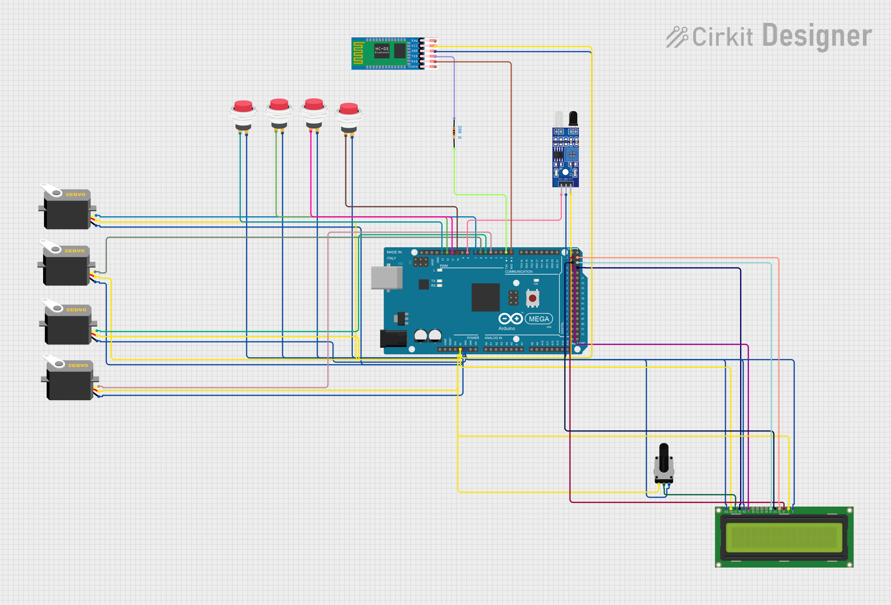 Open Project in Cirkit Designer
Explore Projects Built with RM-series Subminiature Rotary Switch
Open Project in Cirkit DesignerOpen Project in Cirkit DesignerOpen Project in Cirkit DesignerOpen Project in Cirkit DesignerCommon Applications:
- Mode selection in audio and video equipment
- Signal routing in communication devices
- Function switching in industrial control systems
- User interface controls in consumer electronics
Technical Specifications
Key Technical Details:
- Switch Type: Rotary, subminiature
- Number of Positions: 2 to 12 positions (depending on model)
- Contact Rating: 0.5A at 125VAC or 0.2A at 250VAC
- Contact Resistance: ≤ 50 mΩ
- Insulation Resistance: ≥ 100 MΩ at 500VDC
- Dielectric Strength: 500VAC for 1 minute
- Operating Temperature Range: -25°C to +85°C
- Mechanical Life: 10,000 cycles minimum
- Mounting Style: PCB or panel mount
- Actuation Torque: 2.5 to 5.0 N·cm
Pin Configuration and Descriptions:
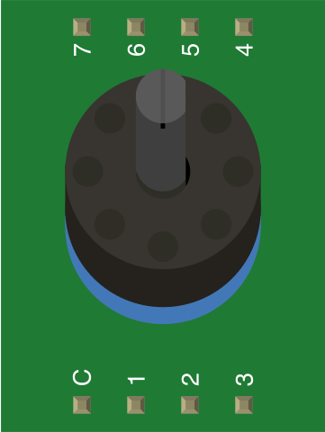
The RM-series rotary switch typically has a common pin (COM) and multiple output pins corresponding to the number of positions. Below is an example pinout for a 6-position rotary switch:
| Pin Number | Description |
|---|---|
| 1 | Output for Position 1 |
| 2 | Output for Position 2 |
| 3 | Output for Position 3 |
| 4 | Output for Position 4 |
| 5 | Output for Position 5 |
| 6 | Output for Position 6 |
| COM | Common pin (shared input/output) |
Note: The number of output pins will vary depending on the specific model and number of positions.
Usage Instructions
How to Use the RM-series Rotary Switch in a Circuit:
- Determine the Number of Positions: Identify the specific model of the RM-series switch and the number of positions it supports (e.g., 6-position, 12-position).
- Connect the Common Pin (COM): Connect the common pin to the input signal or voltage source.
- Connect Output Pins: Connect the output pins to the desired circuit paths or components. Each output pin corresponds to a specific switch position.
- Mount the Switch: Secure the switch to the PCB or panel using the appropriate mounting method (e.g., soldering or panel nut).
- Test the Circuit: Rotate the switch to each position and verify that the correct circuit path is activated.
Important Considerations and Best Practices:
- Voltage and Current Ratings: Ensure the switch is used within its specified voltage and current ratings to avoid damage.
- Debouncing: Rotary switches may produce electrical noise (bouncing) when switching positions. Use a debouncing circuit or software to ensure stable operation.
- Mechanical Life: Avoid excessive force when rotating the switch to maintain its mechanical integrity and lifespan.
- PCB Design: When using the switch in a PCB design, ensure proper spacing and alignment of the pins to avoid short circuits.
Example: Connecting the RM-series Rotary Switch to an Arduino UNO
The following example demonstrates how to use a 6-position RM-series rotary switch with an Arduino UNO to read the selected position.
Circuit Connections:
- Connect the COM pin of the rotary switch to the Arduino's 5V pin.
- Connect each output pin (1 to 6) to a separate digital input pin on the Arduino (e.g., pins 2 to 7).
- Use pull-down resistors (10kΩ) on each digital input pin to ensure stable readings.
Arduino Code:
// Define the digital pins connected to the rotary switch outputs
const int switchPins[] = {2, 3, 4, 5, 6, 7};
const int numPositions = 6;

void setup() {
  Serial.begin(9600); // Initialize serial communication for debugging
  for (int i = 0; i < numPositions; i++) {
    pinMode(switchPins[i], INPUT_PULLDOWN); // Set pins as input with pull-down resistors
  }
}

void loop() {
  for (int i = 0; i < numPositions; i++) {
    if (digitalRead(switchPins[i]) == HIGH) {
      Serial.print("Switch Position: ");
      Serial.println(i + 1); // Print the active position (1-based index)
      delay(500); // Debounce delay
    }
  }
}
Note: Modify the pin numbers in the code to match your specific wiring.
Troubleshooting and FAQs
Common Issues:
Switch Not Responding:
- Cause: Loose or incorrect connections.
- Solution: Verify all connections, especially the common pin and output pins.
Incorrect Position Detected:
- Cause: Electrical noise or bouncing.
- Solution: Add a debouncing circuit or implement software debouncing in your code.
Switch Feels Stiff or Loose:
- Cause: Mechanical wear or improper mounting.
- Solution: Check the mounting and ensure the switch is not subjected to excessive force.
Short Circuits on PCB:
- Cause: Pins too close or solder bridges.
- Solution: Inspect the PCB layout and solder joints for any shorts.
FAQs:
Q: Can the RM-series rotary switch handle DC voltages?
- A: Yes, it can handle DC voltages within its specified ratings (e.g., 0.5A at 125VAC or 0.2A at 250VAC).
Q: How do I clean a rotary switch?
- A: Use a contact cleaner spray designed for electronic components. Avoid excessive moisture.
Q: Can I use the switch for analog signals?
- A: Yes, but ensure the signal levels are within the switch's voltage and current ratings.
Q: What is the lifespan of the RM-series rotary switch?
- A: The switch is rated for a minimum of 10,000 mechanical cycles under normal operating conditions.
By following this documentation, you can effectively integrate the RM-series Subminiature Rotary Switch into your projects and troubleshoot any issues that arise.