How to Use ESP32 Expansion Board: Examples, Pinouts, and Specs
Introduction
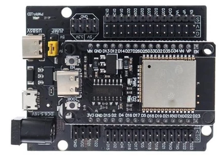
The ESP32 Expansion Board is a versatile development board that integrates the ESP32 microcontroller. It provides additional features such as USB connectivity, power regulation, and easy access to GPIO pins, making it ideal for prototyping and development. The ESP32 microcontroller is known for its robust performance, featuring Wi-Fi and Bluetooth capabilities, making it suitable for a wide range of IoT applications.
Explore Projects Built with ESP32 Expansion Board
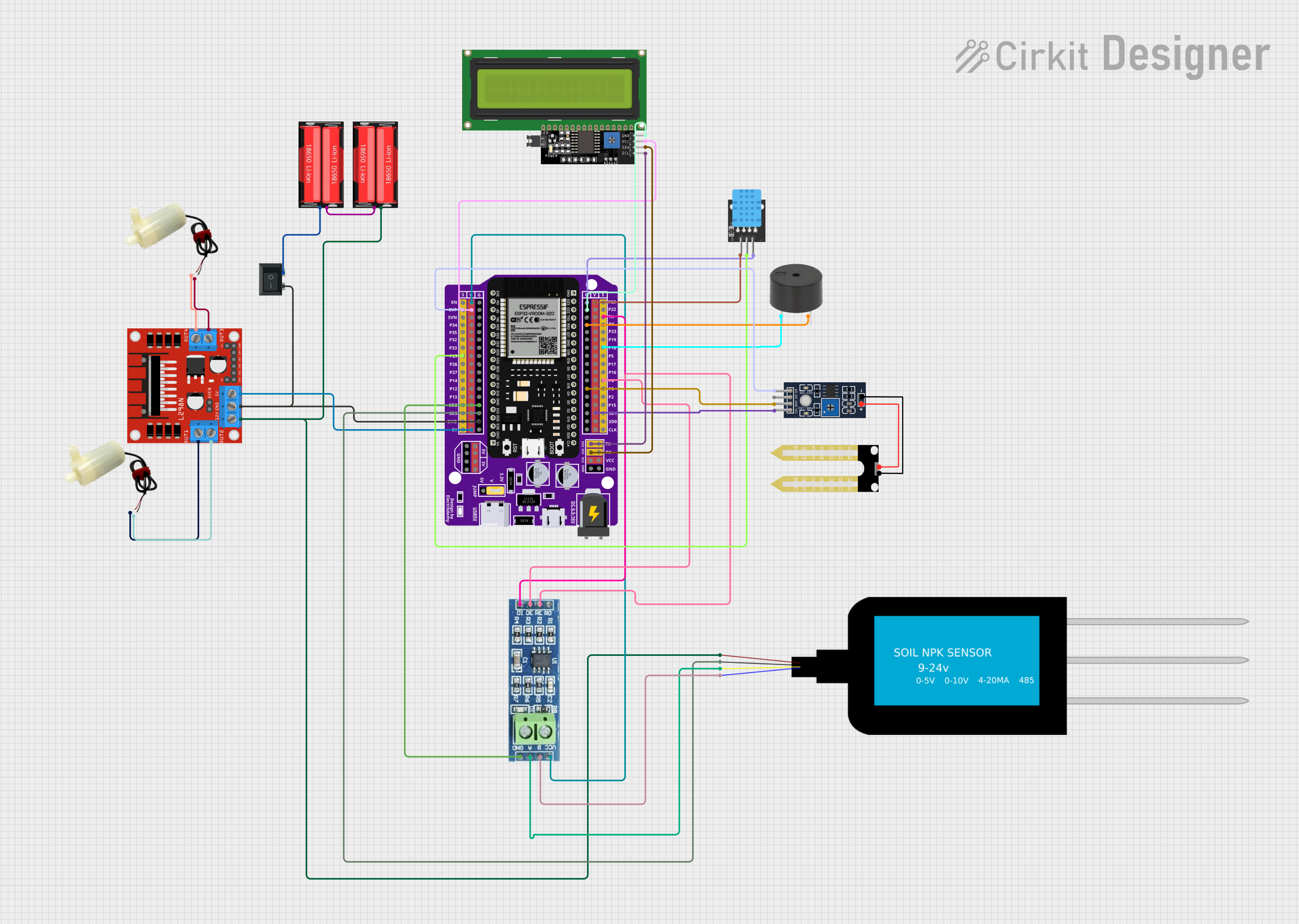

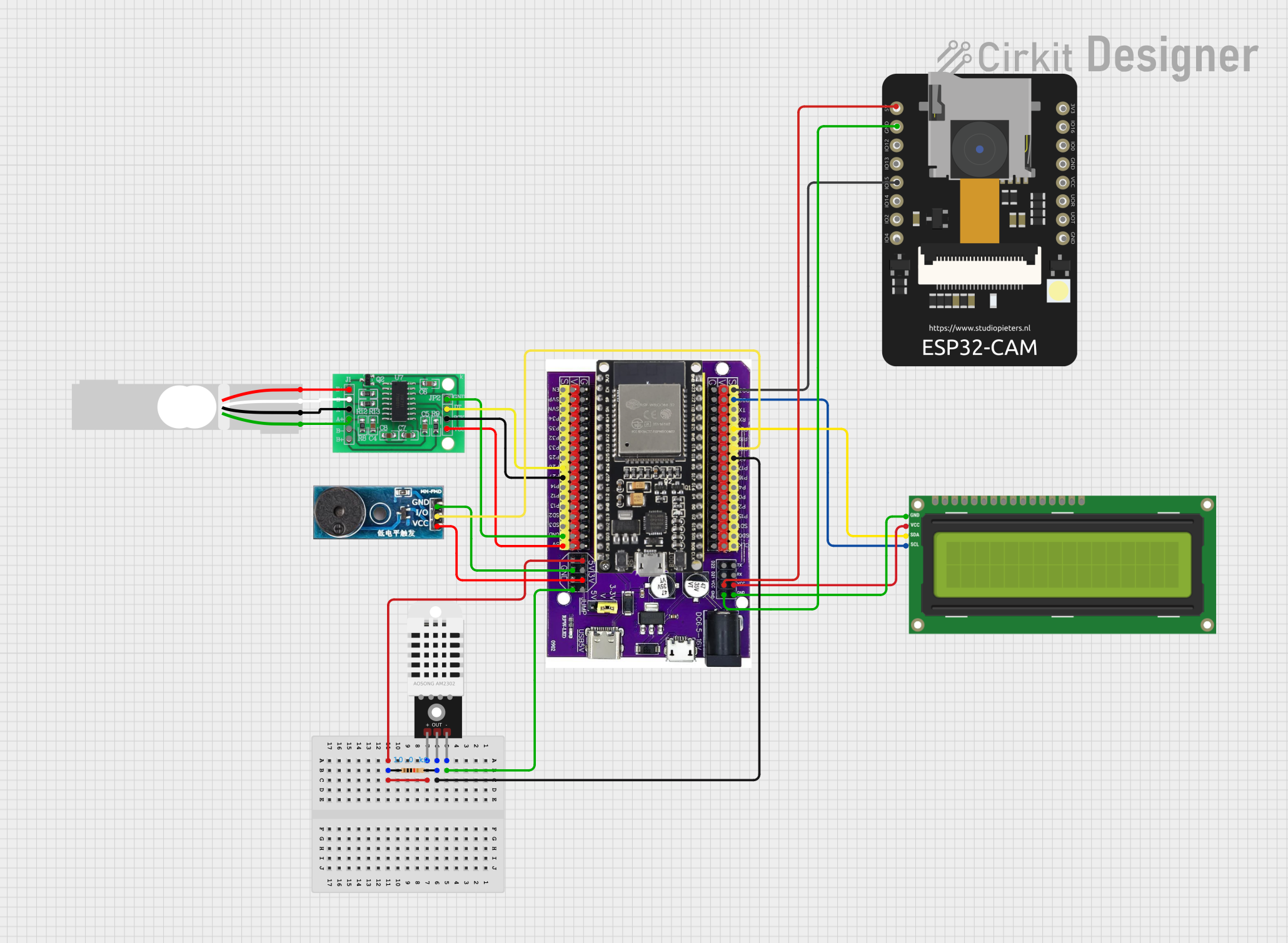
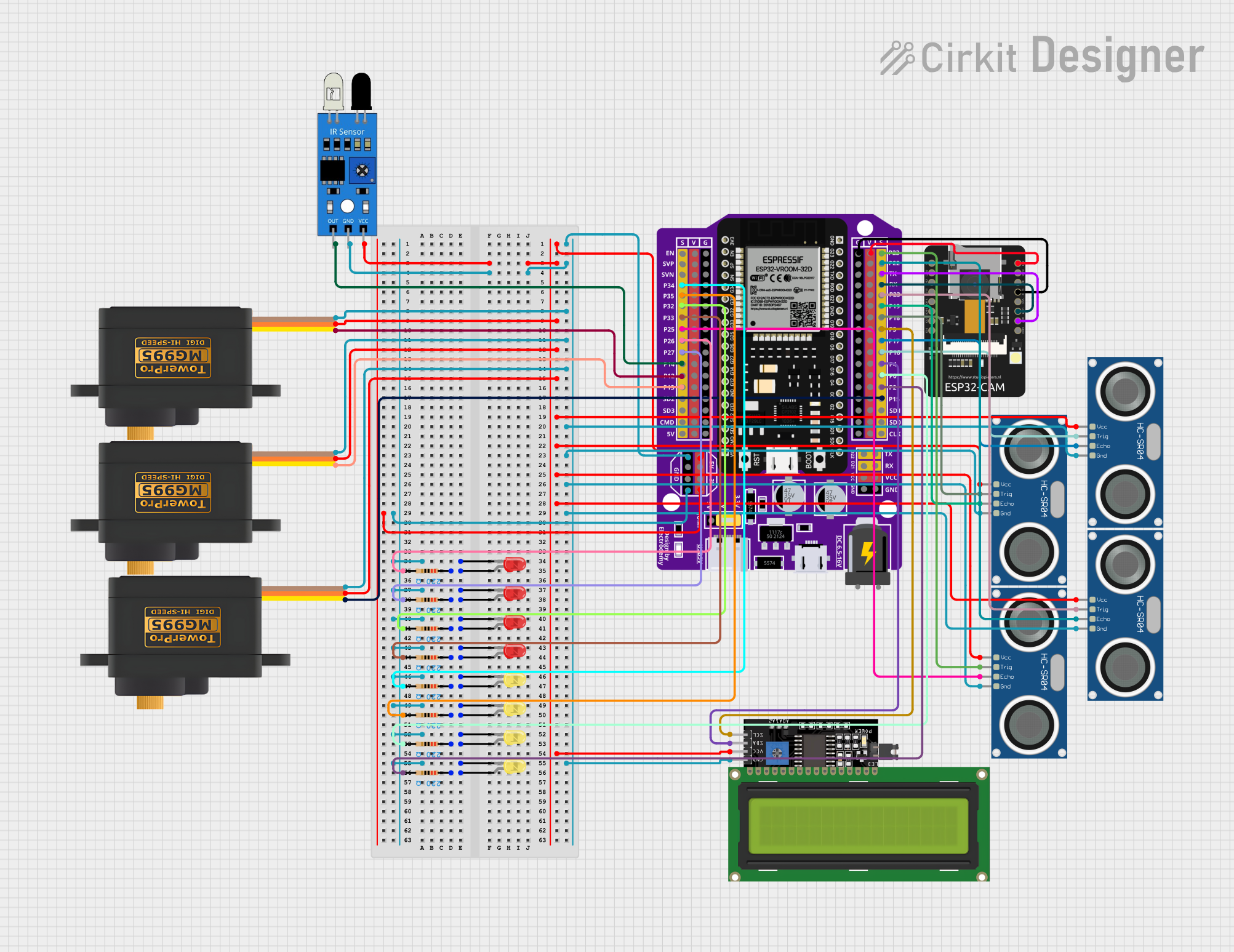
Explore Projects Built with ESP32 Expansion Board
Common Applications and Use Cases
- IoT Projects: Smart home devices, environmental monitoring, and industrial automation.
- Wearable Technology: Fitness trackers, smartwatches, and health monitoring devices.
- Wireless Communication: Wi-Fi and Bluetooth-based applications.
- Prototyping and Development: Rapid development of embedded systems and proof-of-concept projects.
Technical Specifications
Key Technical Details
| Specification | Value |
|---|---|
| Microcontroller | ESP32 |
| Operating Voltage | 3.3V |
| Input Voltage | 5V (via USB) |
| Digital I/O Pins | 34 |
| Analog Input Pins | 16 (ADC) |
| Analog Output Pins | 2 (DAC) |
| Flash Memory | 4MB |
| SRAM | 520KB |
| Communication | Wi-Fi, Bluetooth, UART, SPI, I2C, I2S |
| USB Connectivity | Micro USB |
| Power Regulation | Onboard 3.3V regulator |
Pin Configuration and Descriptions
| Pin Number | Pin Name | Description |
|---|---|---|
| 1 | GND | Ground |
| 2 | 3V3 | 3.3V Power Output |
| 3 | EN | Enable (Active High) |
| 4 | IO23 | GPIO23 (Digital I/O) |
| 5 | IO22 | GPIO22 (Digital I/O) |
| 6 | IO21 | GPIO21 (Digital I/O) |
| 7 | IO19 | GPIO19 (Digital I/O) |
| 8 | IO18 | GPIO18 (Digital I/O) |
| 9 | IO17 | GPIO17 (Digital I/O) |
| 10 | IO16 | GPIO16 (Digital I/O) |
| 11 | IO15 | GPIO15 (Digital I/O) |
| 12 | IO14 | GPIO14 (Digital I/O) |
| 13 | IO13 | GPIO13 (Digital I/O) |
| 14 | IO12 | GPIO12 (Digital I/O) |
| 15 | IO11 | GPIO11 (Digital I/O) |
| 16 | IO10 | GPIO10 (Digital I/O) |
| 17 | IO9 | GPIO9 (Digital I/O) |
| 18 | IO8 | GPIO8 (Digital I/O) |
| 19 | IO7 | GPIO7 (Digital I/O) |
| 20 | IO6 | GPIO6 (Digital I/O) |
| 21 | IO5 | GPIO5 (Digital I/O) |
| 22 | IO4 | GPIO4 (Digital I/O) |
| 23 | IO3 | GPIO3 (Digital I/O) |
| 24 | IO2 | GPIO2 (Digital I/O) |
| 25 | IO1 | GPIO1 (Digital I/O) |
| 26 | IO0 | GPIO0 (Digital I/O) |
| 27 | ADC1 | Analog Input 1 |
| 28 | ADC2 | Analog Input 2 |
| 29 | DAC1 | Analog Output 1 |
| 30 | DAC2 | Analog Output 2 |
| 31 | TX | UART Transmit |
| 32 | RX | UART Receive |
| 33 | SCL | I2C Clock |
| 34 | SDA | I2C Data |
Usage Instructions
How to Use the Component in a Circuit
Powering the Board:
- Connect the board to your computer using a Micro USB cable. This will provide power and enable USB communication.
- Alternatively, you can power the board using an external 5V power supply connected to the 5V pin.
Programming the Board:
- Install the ESP32 board support package in the Arduino IDE.
- Select the appropriate board and port from the Tools menu.
- Write your code and upload it to the board using the Upload button.
Connecting Peripherals:
- Use the GPIO pins to connect sensors, actuators, and other peripherals.
- Ensure that the voltage levels of the connected devices are compatible with the 3.3V logic level of the ESP32.
Important Considerations and Best Practices
- Voltage Levels: Ensure that all connected devices operate at 3.3V to avoid damaging the ESP32.
- Pin Usage: Be mindful of the multifunctionality of the GPIO pins. Some pins have special functions (e.g., ADC, DAC, UART) that may affect their usage.
- Power Supply: When using power-hungry peripherals, ensure that the power supply can provide sufficient current to avoid brownouts.
Example Code
Here is an example code to blink an LED connected to GPIO2 of the ESP32 Expansion Board:
// Define the LED pin
const int ledPin = 2;

void setup() {
  // Initialize the LED pin as an output
  pinMode(ledPin, OUTPUT);
}

void loop() {
  // Turn the LED on
  digitalWrite(ledPin, HIGH);
  delay(1000); // Wait for 1 second

  // Turn the LED off
  digitalWrite(ledPin, LOW);
  delay(1000); // Wait for 1 second
}
Troubleshooting and FAQs
Common Issues Users Might Face
Board Not Detected by Computer:
- Ensure that the USB cable is properly connected and is not damaged.
- Check if the correct drivers are installed for the ESP32 board.
Upload Errors:
- Verify that the correct board and port are selected in the Arduino IDE.
- Press the "EN" button on the board to reset it before uploading the code.
Wi-Fi Connection Issues:
- Ensure that the Wi-Fi credentials are correct.
- Check if the Wi-Fi signal strength is sufficient.
Solutions and Tips for Troubleshooting
- Resetting the Board: Press the "EN" button to reset the board if it becomes unresponsive.
- Serial Monitor: Use the Serial Monitor in the Arduino IDE to debug and view output from the ESP32.
- Power Supply: Ensure that the power supply is stable and can provide sufficient current for the board and connected peripherals.
By following this documentation, users can effectively utilize the ESP32 Expansion Board for their projects, leveraging its powerful features and capabilities.