How to Use IR Sensor Module (LM393): Examples, Pinouts, and Specs
Introduction
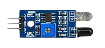
The IR Sensor Module (LM393) is an infrared-based sensor designed to detect obstacles and measure distances by emitting and receiving infrared light. It utilizes the LM393 comparator for signal processing, ensuring reliable and accurate detection. This module is widely used in robotics, automation systems, and proximity detection applications due to its simplicity and effectiveness.
Explore Projects Built with IR Sensor Module (LM393)
Explore Projects Built with IR Sensor Module (LM393)
Common Applications and Use Cases
- Obstacle detection in robotics
- Line-following robots
- Proximity sensing in automation systems
- Object counting and detection
- Security systems and motion detection
Technical Specifications
The IR Sensor Module (LM393) is equipped with the following technical features:
| Parameter | Specification |
|---|---|
| Operating Voltage | 3.3V to 5V DC |
| Current Consumption | 20mA (typical) |
| Detection Range | 2cm to 30cm (adjustable via potentiometer) |
| Output Type | Digital (High/Low) |
| Comparator Chip | LM393 |
| Infrared Wavelength | 760nm to 1100nm |
| Dimensions | ~3.1cm x 1.5cm x 0.7cm |
Pin Configuration and Descriptions
The module typically has a 3-pin interface:
| Pin | Name | Description |
|---|---|---|
| 1 | VCC | Power supply pin. Connect to 3.3V or 5V DC. |
| 2 | GND | Ground pin. Connect to the ground of the power supply. |
| 3 | OUT | Digital output pin. Outputs HIGH (1) when no obstacle is detected, LOW (0) when an obstacle is detected. |
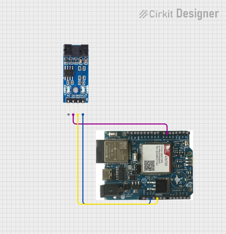
Usage Instructions
How to Use the IR Sensor Module in a Circuit
- Power the Module: Connect the
VCCpin to a 3.3V or 5V power source and theGNDpin to the ground. - Connect the Output: Connect the
OUTpin to a digital input pin of your microcontroller (e.g., Arduino UNO). - Adjust the Sensitivity: Use the onboard potentiometer to adjust the detection range. Turn clockwise to increase the range and counterclockwise to decrease it.
- Test the Module: Place an object within the detection range and observe the
OUTpin. The onboard LED will also light up when an obstacle is detected.
Important Considerations and Best Practices
- Ambient Light Interference: Avoid using the module in environments with strong infrared sources (e.g., direct sunlight) as it may affect accuracy.
- Distance Calibration: Always calibrate the detection range using the potentiometer for your specific application.
- Power Supply: Ensure a stable power supply to avoid erratic behavior.
- Mounting: Position the module so that the IR transmitter and receiver are unobstructed for optimal performance.
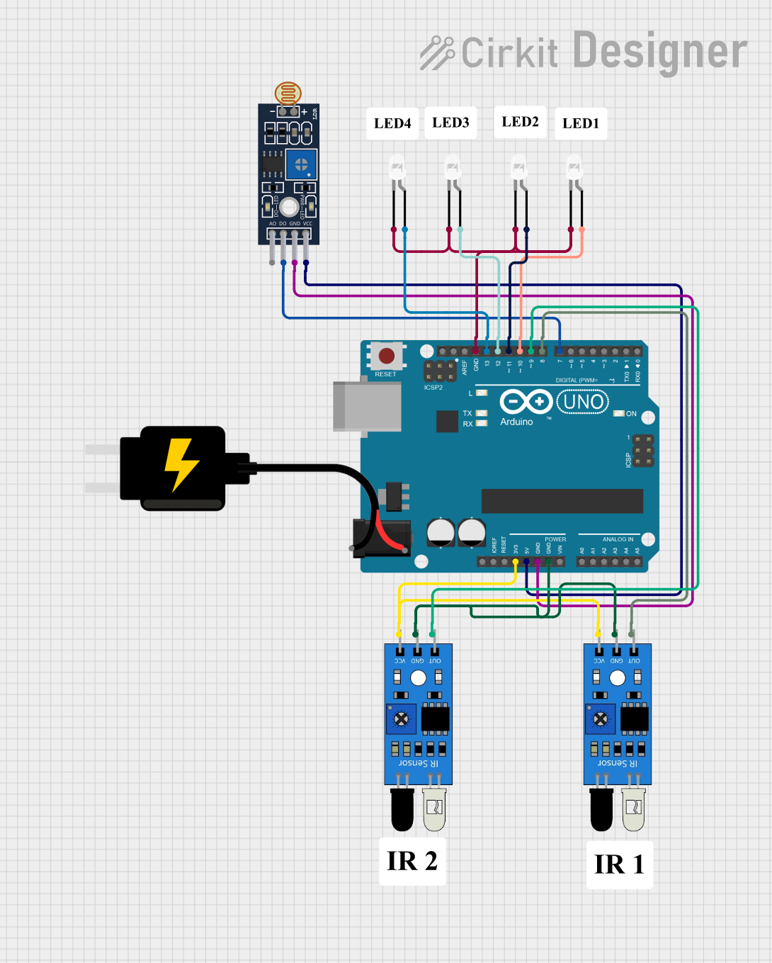
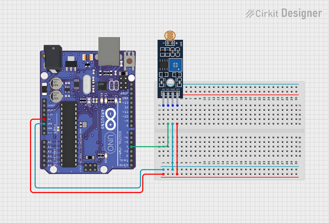
Example: Connecting to an Arduino UNO
Below is an example of how to connect and use the IR Sensor Module with an Arduino UNO:
Circuit Connections
- Connect the
VCCpin of the module to the 5V pin on the Arduino. - Connect the
GNDpin of the module to the GND pin on the Arduino. - Connect the
OUTpin of the module to digital pin 2 on the Arduino.
Arduino Code
// IR Sensor Module Example Code
// This code reads the digital output of the IR sensor and prints the status
// to the Serial Monitor. The onboard LED on pin 13 will also toggle based
// on the sensor's output.

const int irSensorPin = 2;  // IR sensor output connected to digital pin 2
const int ledPin = 13;      // Onboard LED pin

void setup() {
  pinMode(irSensorPin, INPUT);  // Set IR sensor pin as input
  pinMode(ledPin, OUTPUT);      // Set LED pin as output
  Serial.begin(9600);           // Initialize serial communication
}

void loop() {
  int sensorValue = digitalRead(irSensorPin);  // Read the sensor output

  if (sensorValue == LOW) {
    // Obstacle detected
    digitalWrite(ledPin, HIGH);  // Turn on LED
    Serial.println("Obstacle detected!");
  } else {
    // No obstacle
    digitalWrite(ledPin, LOW);   // Turn off LED
    Serial.println("No obstacle.");
  }

  delay(100);  // Small delay for stability
}
Troubleshooting and FAQs
Common Issues and Solutions
The sensor is not detecting obstacles:
- Ensure the module is powered correctly (check
VCCandGNDconnections). - Adjust the potentiometer to calibrate the detection range.
- Verify that the object is within the detection range (2cm to 30cm).
- Ensure the module is powered correctly (check
False detections or erratic behavior:
- Check for interference from ambient light or other infrared sources.
- Use a stable power supply to avoid noise in the circuit.
The onboard LED does not light up:
- Confirm that the module is receiving power.
- Check the
OUTpin connection and ensure it is properly connected to the microcontroller.
The detection range is too short:
- Adjust the potentiometer to increase the range.
- Ensure the object being detected has a reflective surface for better IR reflection.
FAQs
Q: Can the IR Sensor Module detect transparent objects?
A: No, the module may struggle to detect transparent or highly absorbent surfaces as they do not reflect infrared light effectively.
Q: Can I use this module with a 3.3V microcontroller?
A: Yes, the module supports an operating voltage of 3.3V to 5V, making it compatible with 3.3V systems.
Q: How do I increase the detection range beyond 30cm?
A: The detection range is hardware-limited. For longer ranges, consider using a different sensor designed for extended distances.
Q: Is the module suitable for outdoor use?
A: The module can be used outdoors, but strong sunlight or other infrared sources may interfere with its performance. Use shielding or filters if necessary.