Cirkit Designer Logo
Cirkit Designer
Your all-in-one circuit design IDE
Home / 
Component Documentation

How to Use em-18 rfid module: Examples, Pinouts, and Specs

Image of em-18 rfid module
Cirkit Designer LogoDesign with em-18 rfid module in Cirkit Designer

Introduction

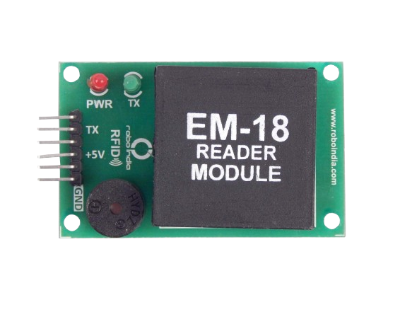
The EM-18 RFID module is a low-cost device used for reading RFID tags. It operates at a frequency of 125 kHz and can read tags within a range of 5-10 cm. The module outputs the tag data in serial format, making it easy to interface with microcontrollers and other digital systems. This makes it an ideal choice for applications such as access control, inventory management, and asset tracking.

Explore Projects Built with em-18 rfid module

Use Cirkit Designer to design, explore, and prototype these projects online. Some projects support real-time simulation. Click "Open Project" to start designing instantly!
ESP32-Based Multi-Authentication System with RFID, Keypad, and Fingerprint Sensor
Image of PEE: A project utilizing em-18 rfid module in a practical application
This circuit integrates an ESP32 microcontroller with an RFID-RC522 module, a Membrane Matrix Keypad, and an R307 Fingerprint Sensor. The ESP32 handles input from the keypad and fingerprint sensor, and communicates with the RFID module for authentication purposes, making it suitable for access control systems.
Cirkit Designer LogoOpen Project in Cirkit Designer
Biometric Access Control System with RFID and Touch Activation
Image of DOORLOCK1: A project utilizing em-18 rfid module in a practical application
This circuit is designed for security and identification purposes, featuring an RFID-RC522 module for contactless communication and a fingerprint scanner for biometric authentication. It includes an LCD display for user interaction, a touch sensor for input, a buzzer for audio feedback, and a relay module for controlling external devices. The components are interfaced with a NANO Expansion board, which likely contains a microcontroller to coordinate the operations of the system.
Cirkit Designer LogoOpen Project in Cirkit Designer
Arduino and ESP8266 RFID Door Lock System with WiFi Connectivity
Image of SmartDoorLock: A project utilizing em-18 rfid module in a practical application
This circuit features an Arduino UNO connected to an RFID-RC522 module for RFID scanning and an ESP8266 ESP-12E WiFi module for wireless communication. The Arduino controls a KY-019 Relay module, which in turn drives a 12V solenoid lock, allowing the lock to be actuated based on RFID card detection or potentially remote commands via WiFi. The Arduino's embedded code is set up to initialize the RFID reader and output the UID of scanned cards to the serial monitor.
Cirkit Designer LogoOpen Project in Cirkit Designer
ESP8266-Based GPS and RFID Tracking System with SIM800L and Wi-Fi Connectivity
Image of FYP: A project utilizing em-18 rfid module in a practical application
This circuit integrates a GPS module, an RFID reader, and a GSM module with an ESP-8266 microcontroller to collect and transmit location and RFID data over Wi-Fi to a backend server. The GPS module provides location data, the RFID reader scans tags, and the GSM module can be used for cellular communication, all powered by a 3.7V battery.
Cirkit Designer LogoOpen Project in Cirkit Designer

Explore Projects Built with em-18 rfid module

Use Cirkit Designer to design, explore, and prototype these projects online. Some projects support real-time simulation. Click "Open Project" to start designing instantly!
Image of PEE: A project utilizing em-18 rfid module in a practical application
ESP32-Based Multi-Authentication System with RFID, Keypad, and Fingerprint Sensor
This circuit integrates an ESP32 microcontroller with an RFID-RC522 module, a Membrane Matrix Keypad, and an R307 Fingerprint Sensor. The ESP32 handles input from the keypad and fingerprint sensor, and communicates with the RFID module for authentication purposes, making it suitable for access control systems.
Cirkit Designer LogoOpen Project in Cirkit Designer
Image of DOORLOCK1: A project utilizing em-18 rfid module in a practical application
Biometric Access Control System with RFID and Touch Activation
This circuit is designed for security and identification purposes, featuring an RFID-RC522 module for contactless communication and a fingerprint scanner for biometric authentication. It includes an LCD display for user interaction, a touch sensor for input, a buzzer for audio feedback, and a relay module for controlling external devices. The components are interfaced with a NANO Expansion board, which likely contains a microcontroller to coordinate the operations of the system.
Cirkit Designer LogoOpen Project in Cirkit Designer
Image of SmartDoorLock: A project utilizing em-18 rfid module in a practical application
Arduino and ESP8266 RFID Door Lock System with WiFi Connectivity
This circuit features an Arduino UNO connected to an RFID-RC522 module for RFID scanning and an ESP8266 ESP-12E WiFi module for wireless communication. The Arduino controls a KY-019 Relay module, which in turn drives a 12V solenoid lock, allowing the lock to be actuated based on RFID card detection or potentially remote commands via WiFi. The Arduino's embedded code is set up to initialize the RFID reader and output the UID of scanned cards to the serial monitor.
Cirkit Designer LogoOpen Project in Cirkit Designer
Image of FYP: A project utilizing em-18 rfid module in a practical application
ESP8266-Based GPS and RFID Tracking System with SIM800L and Wi-Fi Connectivity
This circuit integrates a GPS module, an RFID reader, and a GSM module with an ESP-8266 microcontroller to collect and transmit location and RFID data over Wi-Fi to a backend server. The GPS module provides location data, the RFID reader scans tags, and the GSM module can be used for cellular communication, all powered by a 3.7V battery.
Cirkit Designer LogoOpen Project in Cirkit Designer

Technical Specifications

Key Technical Details

Parameter Value
Operating Voltage 4.5V - 5.5V
Operating Current 50mA
Frequency 125 kHz
Read Range 5-10 cm
Output Format Serial (TTL)
Baud Rate 9600 bps

Pin Configuration and Descriptions

Pin Number Pin Name Description
1 VCC Power supply (4.5V - 5.5V)
2 GND Ground
3 TX Serial data output (TTL level)
4 RX Serial data input (TTL level, usually not used)
5 ANT Antenna
6 LED LED indicator (active low)
7 BEEP Buzzer output (active low)
8 SEL Mode selection (usually connected to GND)

Usage Instructions

How to Use the Component in a Circuit

  1. Power Supply: Connect the VCC pin to a 5V power supply and the GND pin to the ground.
  2. Serial Communication: Connect the TX pin to the RX pin of a microcontroller (e.g., Arduino UNO) to receive the tag data.
  3. Antenna: Ensure the antenna is properly connected to the ANT pin.
  4. LED and Buzzer: Optionally, connect the LED and BEEP pins to an LED and a buzzer, respectively, to get visual and audio feedback when a tag is read.

Important Considerations and Best Practices

  • Power Supply: Ensure a stable 5V power supply to avoid erratic behavior.
  • Read Range: The read range can be affected by the orientation and type of RFID tag used.
  • Interference: Avoid placing the module near metal objects or other electronic devices that may cause interference.
  • Serial Communication: Ensure the baud rate of the microcontroller matches the module's baud rate (9600 bps).

Example Circuit with Arduino UNO

**Connections:**
- EM-18 VCC to Arduino 5V
- EM-18 GND to Arduino GND
- EM-18 TX to Arduino RX (Pin 0)

Example Code for Arduino UNO

#include <SoftwareSerial.h>

// Create a software serial object to communicate with the EM-18 module
SoftwareSerial rfid(2, 3); // RX, TX

void setup() {
  Serial.begin(9600); // Initialize serial communication with the computer
  rfid.begin(9600);   // Initialize serial communication with the EM-18 module
  Serial.println("RFID Reader Initialized");
}

void loop() {
  if (rfid.available()) { // Check if data is available from the EM-18 module
    String tag = "";
    while (rfid.available()) {
      char c = rfid.read(); // Read the incoming data
      tag += c; // Append the data to the tag string
    }
    Serial.print("Tag: ");
    Serial.println(tag); // Print the tag data to the serial monitor
  }
}

Troubleshooting and FAQs

Common Issues Users Might Face

  1. No Data Output: Ensure the connections are correct and the power supply is stable.
  2. Short Read Range: Check for interference and ensure the tag is within the specified range.
  3. Erratic Behavior: Verify the power supply voltage and ensure proper grounding.

Solutions and Tips for Troubleshooting

  • Check Connections: Double-check all connections, especially the power and ground.
  • Stable Power Supply: Use a regulated power supply to avoid voltage fluctuations.
  • Interference: Keep the module away from metal objects and other electronic devices.
  • Baud Rate: Ensure the baud rate of the microcontroller matches the module's baud rate (9600 bps).

FAQs

Q: Can the EM-18 module read multiple tags simultaneously? A: No, the EM-18 module can only read one tag at a time.

Q: What is the maximum read range of the EM-18 module? A: The maximum read range is approximately 10 cm, depending on the tag and environmental conditions.

Q: Can the EM-18 module write data to RFID tags? A: No, the EM-18 module is a read-only device and cannot write data to RFID tags.

Q: What type of RFID tags are compatible with the EM-18 module? A: The EM-18 module is compatible with 125 kHz RFID tags.


This documentation provides a comprehensive guide to using the EM-18 RFID module, covering its technical specifications, usage instructions, and troubleshooting tips. Whether you are a beginner or an experienced user, this guide will help you effectively integrate the EM-18 module into your projects.