How to Use PMW3901: Examples, Pinouts, and Specs
Introduction
The PMW3901 is a high-performance optical flow sensor designed for motion detection and tracking applications. Manufactured by Pimoroni Ltd, this sensor leverages advanced algorithms to provide precise motion data, making it an essential component for robotics, drones, and other autonomous systems. Its compact design and robust performance make it suitable for a wide range of applications, including indoor navigation, object tracking, and stabilization systems.
Explore Projects Built with PMW3901


Explore Projects Built with PMW3901
Common Applications
- Autonomous drones for position hold and navigation
- Robotics for motion tracking and obstacle avoidance
- Stabilization systems in gimbals and cameras
- Indoor navigation for mobile devices and robots
Technical Specifications
The PMW3901 is a versatile sensor with the following key technical details:
| Parameter | Value |
|---|---|
| Manufacturer | Pimoroni Ltd |
| Manufacturer Part ID | 1778-PIM453-ND |
| Sensor Type | Optical Flow |
| Operating Voltage | 3.3V |
| Communication Interface | SPI |
| Maximum Frame Rate | 400 frames per second (fps) |
| Field of View (FOV) | 42° x 42° |
| Operating Temperature | -20°C to 85°C |
| Dimensions | 12.5mm x 12.5mm x 2.4mm |
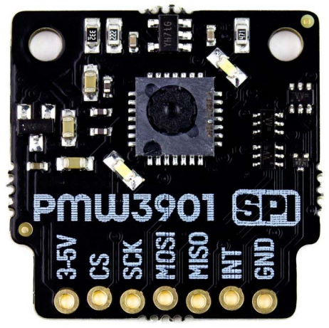
Pin Configuration and Descriptions
The PMW3901 sensor module typically comes with the following pinout:
| Pin Name | Pin Number | Description |
|---|---|---|
| VCC | 1 | Power supply input (3.3V) |
| GND | 2 | Ground |
| MISO | 3 | Master In Slave Out (SPI data output) |
| MOSI | 4 | Master Out Slave In (SPI data input) |
| SCK | 5 | Serial Clock (SPI clock input) |
| CS | 6 | Chip Select (active low) |
| INT | 7 | Interrupt output (optional, for motion detection) |
Usage Instructions
How to Use the PMW3901 in a Circuit
- Power Supply: Connect the VCC pin to a 3.3V power source and the GND pin to ground.
- SPI Communication: Connect the SPI pins (MISO, MOSI, SCK, and CS) to the corresponding SPI pins on your microcontroller or development board.
- Interrupt Pin (Optional): If required, connect the INT pin to a GPIO pin on your microcontroller to handle motion detection interrupts.
- Pull-Up Resistors: Ensure proper pull-up resistors are used on the SPI lines if needed, depending on your microcontroller.
Important Considerations
- Voltage Levels: The PMW3901 operates at 3.3V. Ensure that the SPI lines are also at 3.3V logic levels to avoid damage.
- Mounting: The sensor should be mounted securely to avoid vibrations, which can affect motion data accuracy.
- Lens Cleaning: Keep the sensor's lens clean and free from obstructions for optimal performance.
- SPI Speed: Use an SPI clock speed of up to 2 MHz for reliable communication.
Example Code for Arduino UNO
Below is an example of how to interface the PMW3901 with an Arduino UNO using SPI:
#include <SPI.h>

// Define SPI pins for PMW3901
#define CS_PIN 10  // Chip Select pin
#define MOSI_PIN 11 // Master Out Slave In
#define MISO_PIN 12 // Master In Slave Out
#define SCK_PIN 13  // Serial Clock

void setup() {
  // Initialize Serial Monitor
  Serial.begin(9600);

  // Initialize SPI
  SPI.begin();
  pinMode(CS_PIN, OUTPUT);
  digitalWrite(CS_PIN, HIGH); // Set CS pin high (inactive)

  // Initialize PMW3901
  if (!initializePMW3901()) {
    Serial.println("Failed to initialize PMW3901!");
    while (1); // Halt if initialization fails
  }
  Serial.println("PMW3901 initialized successfully.");
}

void loop() {
  // Read motion data from PMW3901
  int16_t deltaX, deltaY;
  if (readMotionData(&deltaX, &deltaY)) {
    Serial.print("Delta X: ");
    Serial.print(deltaX);
    Serial.print(", Delta Y: ");
    Serial.println(deltaY);
  } else {
    Serial.println("Failed to read motion data.");
  }
  delay(100); // Delay for readability
}

bool initializePMW3901() {
  // Example initialization sequence for PMW3901
  digitalWrite(CS_PIN, LOW); // Select the sensor
  SPI.transfer(0x00); // Example register write
  digitalWrite(CS_PIN, HIGH); // Deselect the sensor
  return true; // Return true if initialization succeeds
}

bool readMotionData(int16_t* deltaX, int16_t* deltaY) {
  // Example function to read motion data
  digitalWrite(CS_PIN, LOW); // Select the sensor
  SPI.transfer(0x02); // Example register read
  *deltaX = SPI.transfer(0x00); // Read delta X
  *deltaY = SPI.transfer(0x00); // Read delta Y
  digitalWrite(CS_PIN, HIGH); // Deselect the sensor
  return true; // Return true if data read succeeds
}
Troubleshooting and FAQs
Common Issues
No Motion Data Output:
- Ensure the SPI connections are correct and secure.
- Verify that the PMW3901 is powered with 3.3V.
- Check the SPI clock speed (should not exceed 2 MHz).
Inaccurate Motion Data:
- Ensure the sensor is mounted securely to avoid vibrations.
- Clean the sensor's lens to remove dust or debris.
- Verify that the sensor is not exposed to excessive light or reflective surfaces.
Initialization Fails:
- Double-check the SPI wiring and ensure the CS pin is correctly configured.
- Verify that the microcontroller's SPI library is properly initialized.
FAQs
Q: Can the PMW3901 be used outdoors?
A: The PMW3901 is primarily designed for indoor use. Outdoor environments with excessive light or reflective surfaces may affect its performance.
Q: What is the maximum range of the PMW3901?
A: The PMW3901 is optimized for short-range motion detection, typically within a few meters.
Q: Can I use the PMW3901 with a 5V microcontroller?
A: Yes, but you must use a level shifter to convert the 5V logic levels to 3.3V to avoid damaging the sensor.
Q: Does the PMW3901 require calibration?
A: The PMW3901 does not require calibration for most applications, but proper mounting and alignment are essential for accurate results.