How to Use KY-010 Módulo Foto Interruptor: Examples, Pinouts, and Specs
Introduction
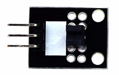
The KY-010 Módulo Foto Interruptor is a light-sensitive module designed to detect light levels using a photoresistor. It is commonly used in projects that require light detection, such as automatic lighting systems, light-sensitive alarms, and other light-based control systems. The module outputs a digital signal, making it easy to interface with microcontrollers like Arduino.
This module is ideal for applications where detecting the presence or absence of light is critical, such as in security systems, environmental monitoring, or interactive projects.
Explore Projects Built with KY-010 Módulo Foto Interruptor

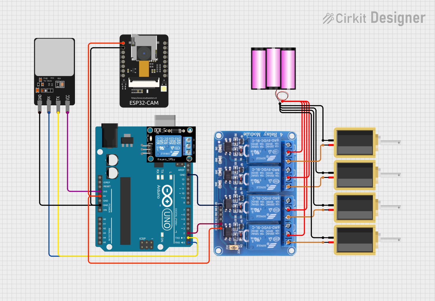

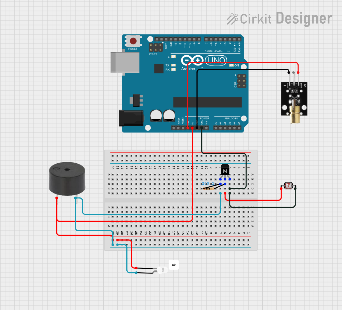
Explore Projects Built with KY-010 Módulo Foto Interruptor
Technical Specifications
- Operating Voltage: 3.3V to 5V
- Output Type: Digital (High/Low)
- Detection Range: Sensitive to visible light
- Dimensions: 18.5mm x 15mm
- Weight: ~2g
Pin Configuration and Descriptions
The KY-010 module has three pins, as described in the table below:
| Pin Name | Description | Connection Details |
|---|---|---|
| Signal | Digital output signal (High/Low) | Connect to a digital input pin on a microcontroller |
| VCC | Power supply input (3.3V to 5V) | Connect to the 3.3V or 5V pin of the microcontroller |
| GND | Ground | Connect to the GND pin of the microcontroller |
Usage Instructions
How to Use the KY-010 in a Circuit
Wiring the Module:
- Connect the VCC pin of the KY-010 to the 5V pin of your microcontroller.
- Connect the GND pin of the KY-010 to the GND pin of your microcontroller.
- Connect the Signal pin of the KY-010 to a digital input pin on your microcontroller (e.g., pin 2 on an Arduino UNO).
Behavior:
- When the module detects light, it outputs a High signal (logic 1).
- When no light is detected, it outputs a Low signal (logic 0).
Example Circuit:
- Use a pull-down resistor (10kΩ) on the Signal pin if needed for stable readings.
- Optionally, connect an LED to visually indicate the module's output.
Arduino UNO Example Code
Below is an example code snippet to use the KY-010 module with an Arduino UNO:
// KY-010 Photoresistor Module Example Code
// This code reads the digital signal from the KY-010 and turns on an LED
// when light is detected.

const int sensorPin = 2;  // KY-010 Signal pin connected to digital pin 2
const int ledPin = 13;    // Built-in LED on Arduino UNO

void setup() {
  pinMode(sensorPin, INPUT);  // Set the sensor pin as input
  pinMode(ledPin, OUTPUT);    // Set the LED pin as output
  Serial.begin(9600);         // Initialize serial communication for debugging
}

void loop() {
  int sensorValue = digitalRead(sensorPin);  // Read the KY-010 output

  if (sensorValue == HIGH) {
    // If light is detected, turn on the LED
    digitalWrite(ledPin, HIGH);
    Serial.println("Light detected!");
  } else {
    // If no light is detected, turn off the LED
    digitalWrite(ledPin, LOW);
    Serial.println("No light detected.");
  }

  delay(100);  // Small delay for stability
}
Important Considerations and Best Practices
- Ensure the module is not exposed to excessive light or heat, as this may affect its performance.
- Use a pull-down resistor if the signal pin shows unstable readings.
- Avoid placing the module in environments with high electrical noise to prevent false readings.
- Test the module in your specific lighting conditions to calibrate its sensitivity.
Troubleshooting and FAQs
Common Issues and Solutions
The module is not detecting light:
- Verify the wiring connections, especially the VCC and GND pins.
- Ensure the light source is within the module's detection range.
- Check the power supply voltage (3.3V to 5V).
Unstable or fluctuating readings:
- Add a pull-down resistor (10kΩ) to the Signal pin.
- Ensure the module is not exposed to electrical noise or interference.
No output signal:
- Confirm that the Signal pin is connected to the correct digital input pin on the microcontroller.
- Test the module with a multimeter to ensure it is functioning properly.
FAQs
Q: Can the KY-010 detect infrared light?
A: No, the KY-010 is designed to detect visible light and is not sensitive to infrared light.
Q: Can I use the KY-010 with a 3.3V microcontroller?
A: Yes, the KY-010 operates within a voltage range of 3.3V to 5V, making it compatible with 3.3V systems.
Q: How can I increase the sensitivity of the module?
A: The sensitivity of the KY-010 is fixed, but you can adjust the placement of the module or use additional optics to focus light onto the sensor.
Q: Is the KY-010 suitable for outdoor use?
A: The KY-010 is not weatherproof. If used outdoors, ensure it is protected from moisture and extreme temperatures.
By following this documentation, you can effectively integrate the KY-010 Módulo Foto Interruptor into your projects for reliable light detection.