How to Use DC Female Jack with Cable: Examples, Pinouts, and Specs
Introduction
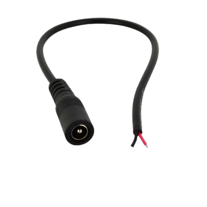
The DC Female Jack with Cable is a versatile connector designed to facilitate the connection of a DC power supply to electronic devices. It features a female socket that securely receives a male DC plug, ensuring a reliable power connection. The attached cable simplifies installation, making it a popular choice for powering DIY electronics, prototyping, and small appliances.
Explore Projects Built with DC Female Jack with Cable


Explore Projects Built with DC Female Jack with Cable
Common Applications and Use Cases
- Powering Arduino, Raspberry Pi, and other microcontroller-based projects
- Connecting DC power supplies to LED strips, motors, and sensors
- Replacing or extending power connectors in consumer electronics
- Prototyping and testing circuits in hobbyist and professional projects
Technical Specifications
The following table outlines the key technical details of the DC Female Jack with Cable:
| Parameter | Specification |
|---|---|
| Connector Type | DC Female Jack |
| Cable Length | Typically 20–30 cm (varies by model) |
| Voltage Rating | Up to 24V DC |
| Current Rating | 2A (standard) |
| Outer Diameter (OD) | 5.5 mm |
| Inner Diameter (ID) | 2.1 mm (common) |
| Cable Wire Gauge | 22 AWG (typical) |
| Polarity | Red: Positive (+), Black: Negative (-) |
Pin Configuration and Descriptions
The DC Female Jack with Cable typically has two wires for connection. The table below describes the wire configuration:
| Wire Color | Function | Description |
|---|---|---|
| Red | Positive (+) | Connects to the positive terminal of the power source |
| Black | Negative (-) | Connects to the ground or negative terminal |
Usage Instructions
How to Use the Component in a Circuit
- Identify Polarity: Ensure you correctly identify the polarity of the wires. The red wire is positive (+), and the black wire is negative (-).
- Connect to Power Source: Solder or connect the wires to the appropriate terminals of your circuit or device. Ensure the red wire connects to the positive terminal and the black wire to the ground.
- Secure the Connection: Use heat shrink tubing or electrical tape to insulate the soldered connections and prevent short circuits.
- Test the Connection: Before powering your device, use a multimeter to verify the polarity and continuity of the connections.
Important Considerations and Best Practices
- Voltage and Current Ratings: Ensure the DC Female Jack with Cable is rated for the voltage and current of your power supply. Exceeding these ratings can damage the connector or your device.
- Polarity Check: Always double-check the polarity of the wires before connecting to avoid damaging your circuit.
- Strain Relief: Use cable ties or clamps to secure the cable and prevent strain on the soldered connections.
- Compatibility: Verify that the male DC plug matches the dimensions (5.5 mm OD, 2.1 mm ID) of the female jack.
Example: Connecting to an Arduino UNO
The DC Female Jack with Cable can be used to power an Arduino UNO via its barrel jack. Below is an example of how to connect it:
- Connect the red wire of the DC Female Jack to the positive terminal of a 9V DC power supply.
- Connect the black wire to the negative terminal of the power supply.
- Plug the male DC plug from the power supply into the Arduino UNO's barrel jack.
Arduino Code Example
If you're powering sensors or modules connected to the Arduino, you can use the following code to test the setup:
// Example code to blink an LED connected to pin 13 on the Arduino UNO
// Ensure the Arduino is powered via the DC Female Jack with Cable

void setup() {
  pinMode(13, OUTPUT); // Set pin 13 as an output pin
}

void loop() {
  digitalWrite(13, HIGH); // Turn the LED on
  delay(1000);            // Wait for 1 second
  digitalWrite(13, LOW);  // Turn the LED off
  delay(1000);            // Wait for 1 second
}
Troubleshooting and FAQs
Common Issues and Solutions
No Power to the Device
- Cause: Incorrect polarity or loose connections.
- Solution: Verify the polarity of the wires and ensure all connections are secure.
Overheating of the Connector
- Cause: Exceeding the current rating of the connector.
- Solution: Use a connector rated for higher current or reduce the load on the circuit.
Intermittent Power
- Cause: Poor soldering or damaged cable.
- Solution: Inspect the solder joints and cable for damage. Resolder or replace as needed.
Connector Does Not Fit
- Cause: Mismatch in dimensions between the male plug and female jack.
- Solution: Ensure the male plug matches the 5.5 mm OD and 2.1 mm ID dimensions of the female jack.
FAQs
Q: Can I use this connector for AC power?
A: No, the DC Female Jack with Cable is designed specifically for DC power. Using it with AC power can be dangerous and may damage the connector or your device.
Q: What is the maximum cable length I can use?
A: While the standard cable length is 20–30 cm, you can extend it. However, longer cables may result in voltage drops, especially at higher currents. Use thicker wires (lower AWG) for longer extensions.
Q: How do I know if the connector is compatible with my power supply?
A: Check the dimensions of the male DC plug on your power supply. It should have a 5.5 mm outer diameter and a 2.1 mm inner diameter to fit the female jack.
Q: Can I use this connector with a battery pack?
A: Yes, as long as the voltage and current ratings of the battery pack are within the specifications of the connector. Ensure proper polarity when connecting.