How to Use SSD1351: Examples, Pinouts, and Specs
Introduction
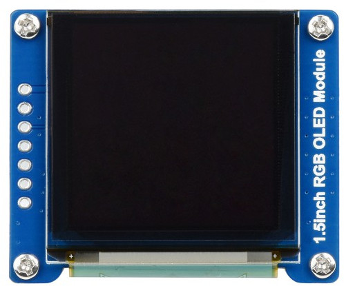
The SSD1351 is a low-power OLED display driver manufactured by Waveshare, designed to drive a 1.5-inch RGB OLED module with a resolution of 128x128 pixels. This module supports both SPI and I2C communication interfaces, making it versatile for integration into various embedded systems. The SSD1351 is known for its vibrant color reproduction, high contrast ratio, and fast response time, making it ideal for applications requiring high-quality graphical displays.
Explore Projects Built with SSD1351
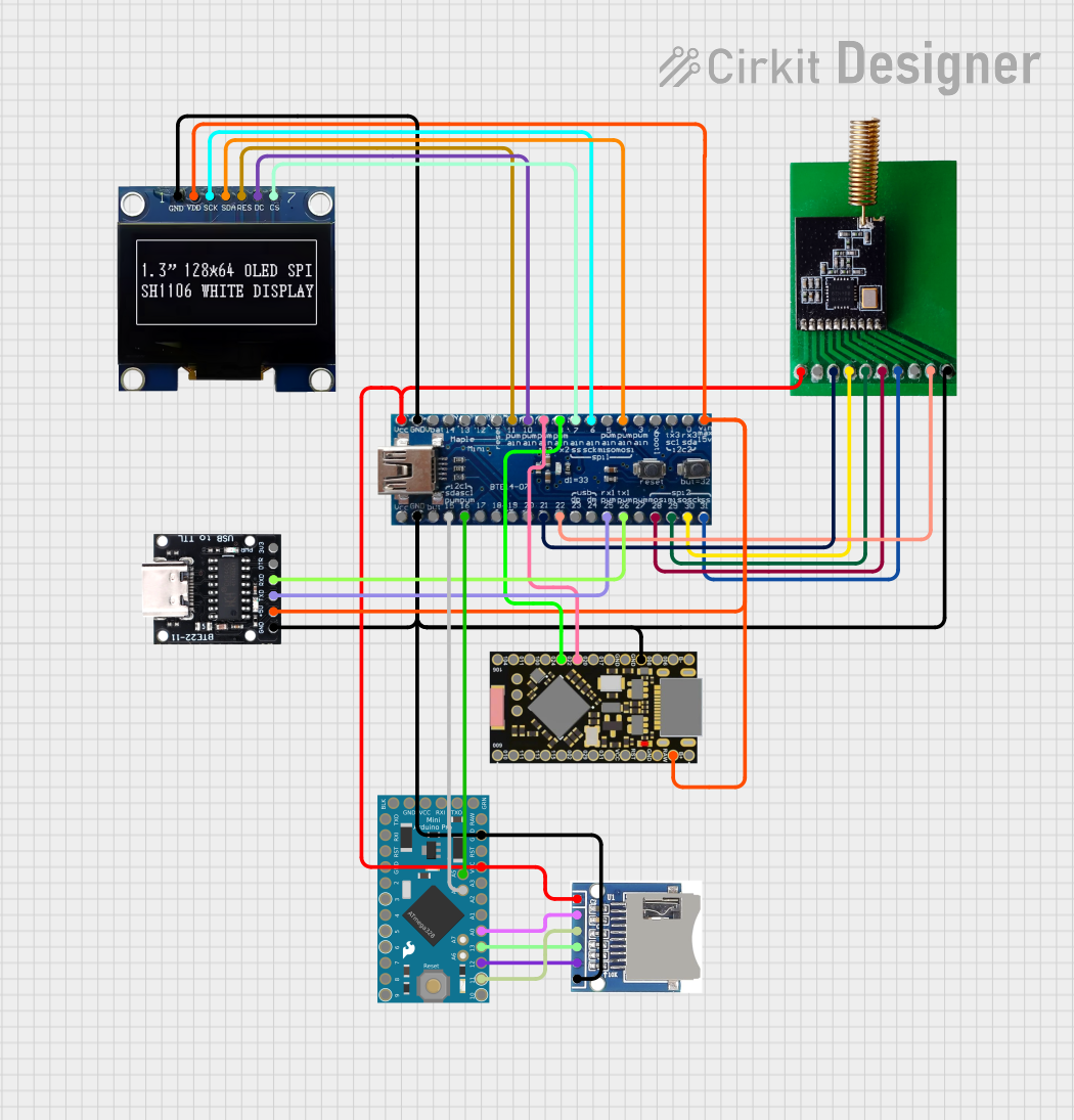
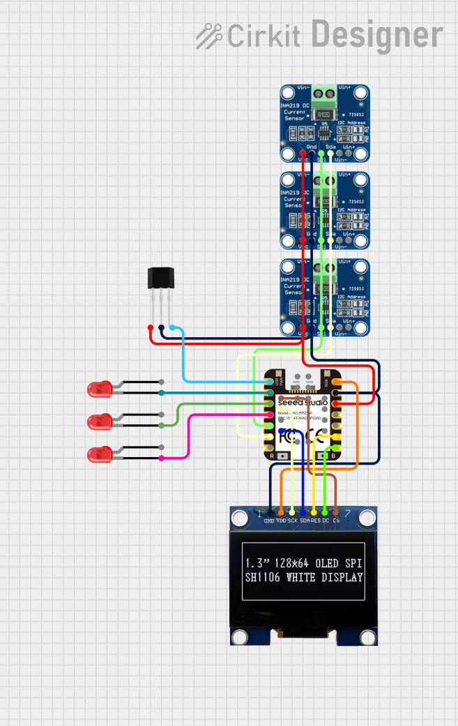
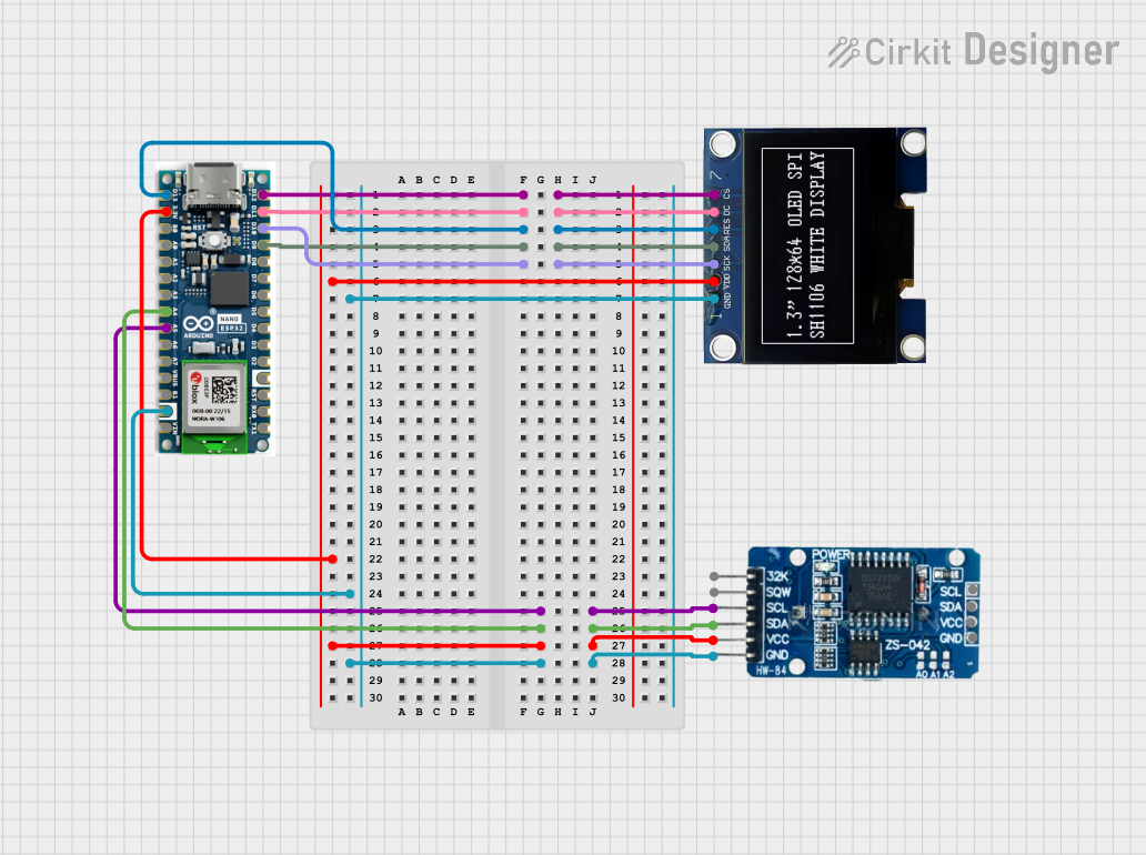

Explore Projects Built with SSD1351
Common Applications and Use Cases
- Wearable devices and smartwatches
- Portable medical devices
- Industrial control panels
- IoT devices with graphical interfaces
- Consumer electronics such as MP3 players and digital cameras
Technical Specifications
Key Technical Details
| Parameter | Value |
|---|---|
| Manufacturer | Waveshare |
| Part ID | 1.5inch RGB OLED Module |
| Display Resolution | 128x128 pixels |
| Display Type | OLED (Organic Light Emitting Diode) |
| Color Depth | 16-bit (65,536 colors) |
| Communication Interface | SPI / I2C |
| Operating Voltage | 3.3V / 5V (logic level) |
| Operating Temperature | -40°C to 85°C |
| Dimensions | 1.5 inches (diagonal) |
| Driver IC | SSD1351 |
Pin Configuration and Descriptions
The SSD1351 module has a 7-pin interface for SPI communication. Below is the pinout description:
| Pin No. | Pin Name | Description |
|---|---|---|
| 1 | GND | Ground pin for power supply |
| 2 | VCC | Power supply pin (3.3V or 5V) |
| 3 | SCL | Serial Clock Line for SPI/I2C communication |
| 4 | SDA | Serial Data Line for SPI/I2C communication |
| 5 | RES | Reset pin (active low) |
| 6 | DC | Data/Command control pin (High for data, Low for command) |
| 7 | CS | Chip Select pin (active low) |
Usage Instructions
How to Use the SSD1351 in a Circuit
- Power Supply: Connect the
VCCpin to a 3.3V or 5V power source and theGNDpin to ground. - Communication Interface: Use SPI or I2C to communicate with the module. For SPI, connect
SCL,SDA,RES,DC, andCSto the corresponding pins on your microcontroller. - Initialization: The SSD1351 requires initialization commands to configure the display settings. These commands are sent via the SPI or I2C interface.
- Data Transmission: Use the
DCpin to differentiate between command and data transmission. SetDClow for commands and high for data. - Reset: Toggle the
RESpin to reset the display before initialization.
Important Considerations and Best Practices
- Ensure the power supply voltage matches the module's requirements (3.3V or 5V).
- Use level shifters if your microcontroller operates at a different logic level than the display.
- Avoid prolonged exposure to static electricity, as it can damage the OLED module.
- Use proper decoupling capacitors near the power supply pins to reduce noise.
- Follow the recommended initialization sequence provided in the SSD1351 datasheet.
Example Code for Arduino UNO
Below is an example of how to interface the SSD1351 with an Arduino UNO using the SPI interface:
#include <Adafruit_GFX.h>      // Graphics library for OLED
#include <Adafruit_SSD1351.h> // SSD1351 driver library
#include <SPI.h>

// Define pin connections
#define OLED_CS   10  // Chip Select pin
#define OLED_DC   9   // Data/Command pin
#define OLED_RST  8   // Reset pin

// Create an instance of the SSD1351 display
Adafruit_SSD1351 display = Adafruit_SSD1351(128, 128, &SPI, OLED_CS, OLED_DC, OLED_RST);

void setup() {
  // Initialize the display
  display.begin();

  // Clear the display with a black background
  display.fillScreen(SSD1351_BLACK);

  // Display a test message
  display.setTextColor(SSD1351_WHITE);
  display.setCursor(0, 0);
  display.println("Hello, SSD1351!");
  display.display();
}

void loop() {
  // Add your code here to update the display
}
Notes:
- Install the
Adafruit_GFXandAdafruit_SSD1351libraries from the Arduino Library Manager before running the code. - Ensure the SPI pins (MOSI, MISO, SCK) on the Arduino UNO are correctly connected to the SSD1351 module.
Troubleshooting and FAQs
Common Issues and Solutions
Display Not Turning On:
- Verify the power supply connections and ensure the correct voltage is applied.
- Check the
RESpin and ensure it is toggled during initialization.
No Output on the Display:
- Ensure the SPI or I2C connections are correct and match the microcontroller's pin configuration.
- Verify that the initialization sequence in the code matches the SSD1351 datasheet.
Flickering or Distorted Display:
- Check for loose connections or poor soldering on the module.
- Add decoupling capacitors near the power supply pins to reduce noise.
Incorrect Colors or Artifacts:
- Ensure the color depth and pixel format settings in the code match the SSD1351's requirements.
- Verify that the
DCpin is correctly toggled between data and command modes.
FAQs
Q: Can I use the SSD1351 with a 5V microcontroller?
A: Yes, but you must use level shifters to convert the 5V logic signals to 3.3V to avoid damaging the module.
Q: How do I switch between SPI and I2C modes?
A: The SSD1351 module is typically configured for SPI by default. Refer to the module's documentation for instructions on enabling I2C mode, if supported.
Q: What is the maximum frame rate supported by the SSD1351?
A: The SSD1351 can achieve a frame rate of up to 60Hz, depending on the communication speed and the complexity of the graphics being displayed.
Q: Can I use the SSD1351 outdoors?
A: While the OLED display offers high contrast, it may not be easily readable in direct sunlight. Consider using it in shaded or indoor environments.