How to Use Solar Charge Controller: Examples, Pinouts, and Specs
Introduction
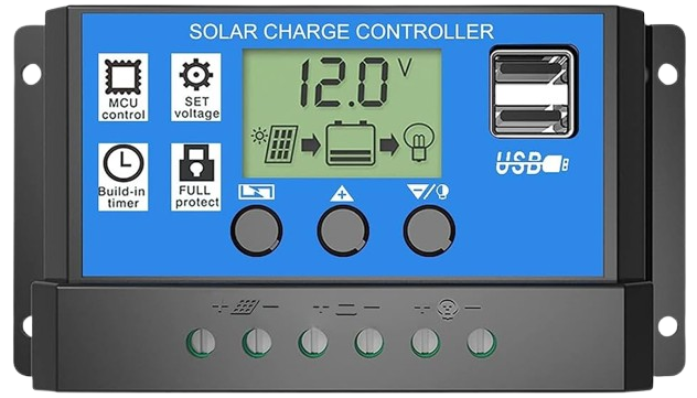
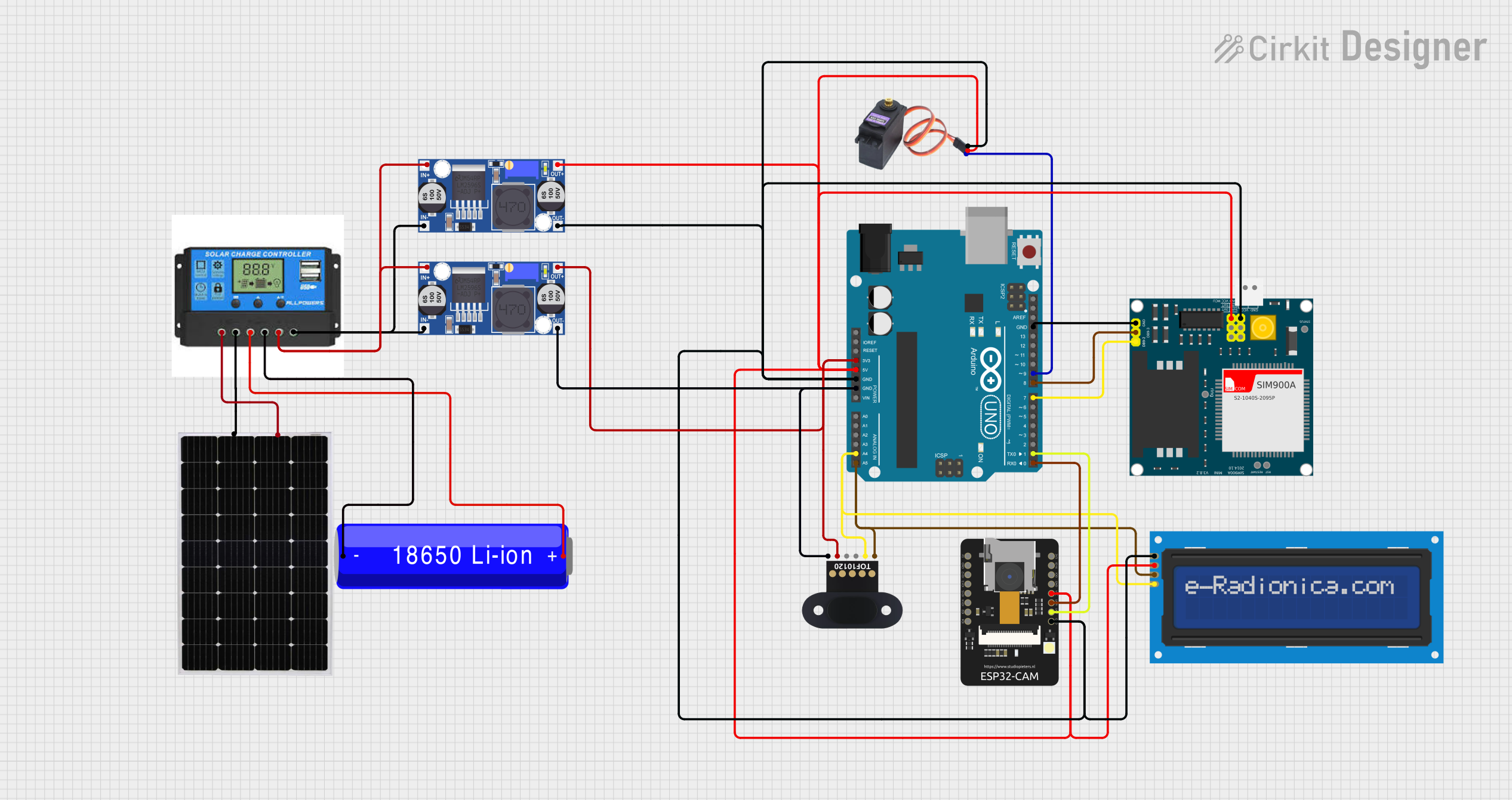
A Solar Charge Controller is an essential component in solar power systems that include batteries. Its primary function is to regulate the voltage and current coming from the solar panels going to the battery. By doing so, it ensures that the batteries are charged efficiently and safely, preventing overcharging and prolonging the battery's lifespan. Solar Charge Controllers are commonly used in various applications such as off-grid solar systems, RV solar systems, and solar lighting systems.
Explore Projects Built with Solar Charge Controller
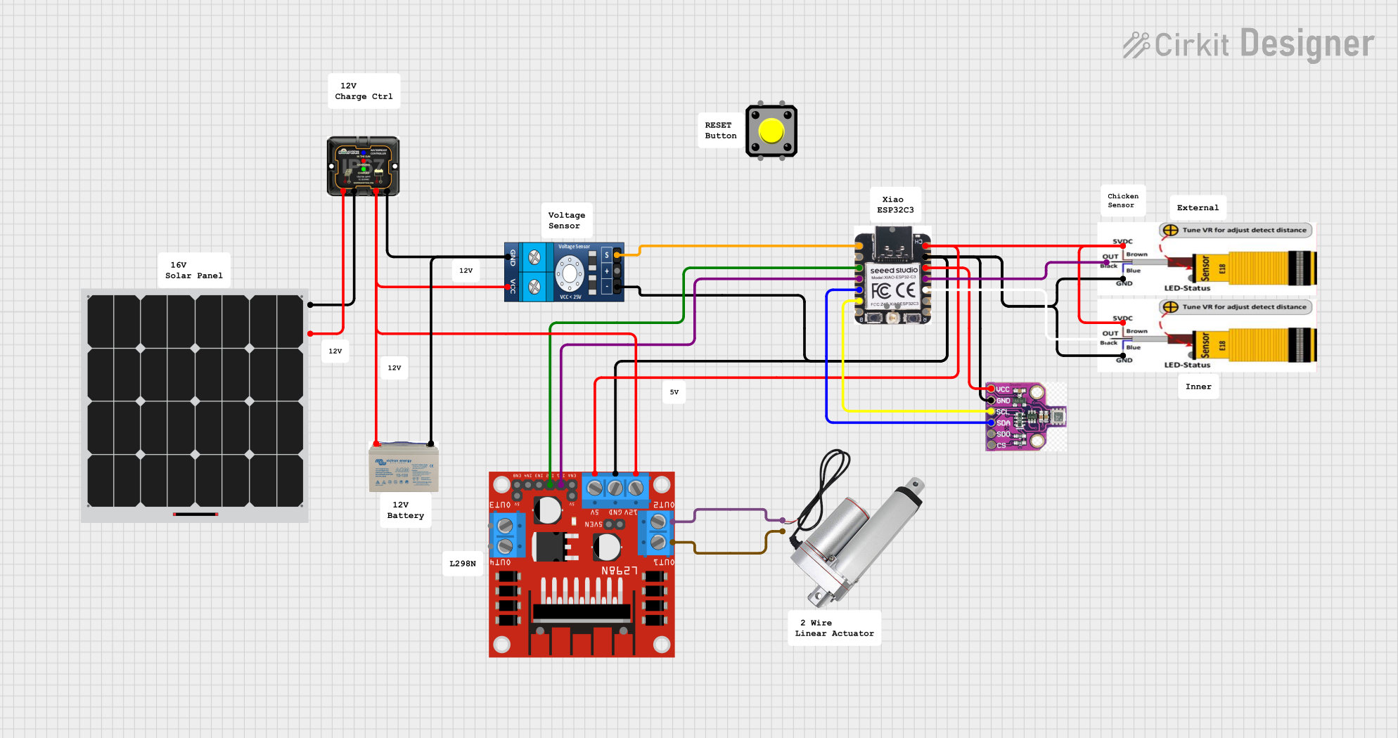
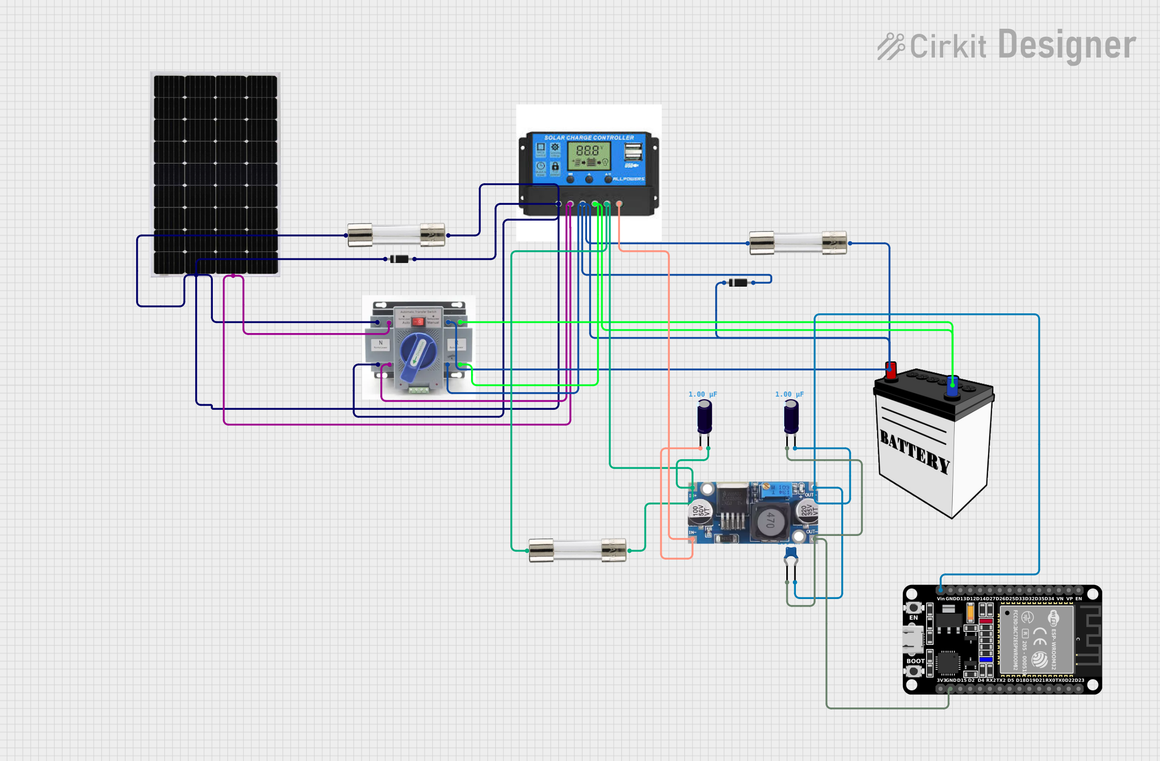
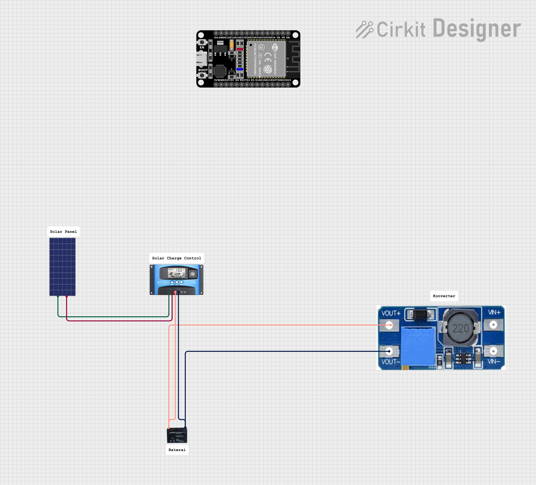
Explore Projects Built with Solar Charge Controller
Technical Specifications
Key Technical Details
- Rated Voltage: Typically 12V or 24V (auto-sensing)
- Maximum Charging Current: Ranges from 10A to 60A (depending on model)
- Maximum Solar Input Voltage: Varies with controller type, often around 50V for PWM and up to 150V for MPPT controllers
- Efficiency: Up to 99% for MPPT controllers
- Self-Consumption: Less than 10mA
- Operating Temperature Range: -35°C to +55°C
Pin Configuration and Descriptions
| Pin/Port | Description |
|---|---|
| PV+ | Positive solar panel input |
| PV- | Negative solar panel input |
| BAT+ | Positive battery connection |
| BAT- | Negative battery connection |
| LOAD+ | Positive load connection (if available) |
| LOAD- | Negative load connection (if available) |
| TEMP | External temperature sensor input (if available) |
| COM | Communication port for monitoring (if available) |
Usage Instructions
How to Use the Component in a Circuit
- Connect the Battery: First, connect the battery to the Solar Charge Controller. Ensure the polarity is correct (BAT+ to battery positive, BAT- to battery negative).
- Connect the Solar Panels: Connect the solar panels to the controller (PV+ to panel positive, PV- to panel negative). Make sure the total voltage and current do not exceed the controller's specifications.
- Connect the Load (Optional): If the controller has a load output, connect your load to LOAD+ and LOAD-. This allows the controller to disconnect the load in case of low battery voltage to prevent deep discharge.
- Set the Controller Parameters: Program the controller according to the battery type and capacity. This may involve setting the charge profile, voltage thresholds, and other parameters.
Important Considerations and Best Practices
- Battery Compatibility: Ensure the controller is compatible with your battery type (e.g., lead-acid, lithium).
- Sizing: The controller should be sized appropriately for the solar panel array and the battery bank.
- Installation: Install the controller in a location protected from direct sunlight and moisture.
- Ventilation: Ensure adequate ventilation around the controller to prevent overheating.
- Safety: Use proper fuses and circuit breakers to protect against overcurrent situations.
Troubleshooting and FAQs
Common Issues
- Battery Not Charging: Check connections, ensure the solar panel is receiving sunlight, and verify that the controller settings match the battery specifications.
- Controller Overheating: Ensure the controller is properly ventilated and not exposed to high temperatures.
- Load Not Operating: Verify that the load is correctly connected and that the controller's low voltage disconnect has not been activated.
Solutions and Tips for Troubleshooting
- Check Connections: Loose or incorrect connections are a common issue. Double-check all wiring.
- Reset Controller: Sometimes a simple reset can resolve issues. Refer to the controller's manual for reset procedures.
- Monitor Performance: Use a multimeter to check the voltage at the battery and the solar panel to ensure proper operation.
FAQs
Q: Can I connect multiple solar panels to one charge controller? A: Yes, as long as the combined voltage and current of the panels do not exceed the controller's specifications.
Q: What is the difference between PWM and MPPT charge controllers? A: PWM (Pulse Width Modulation) controllers are simpler and less expensive but less efficient. MPPT (Maximum Power Point Tracking) controllers are more efficient and can extract more power from the solar panels, especially in varying light conditions.
Q: How do I know if my battery is compatible with the charge controller? A: Check the controller's manual for compatible battery types and ensure the voltage and capacity settings match your battery.
Example Code for Arduino UNO Connection
// This example assumes the use of a PWM Solar Charge Controller with an Arduino UNO
// for monitoring purposes only. Actual charge controller operation is independent of the Arduino.

#include <SoftwareSerial.h>

SoftwareSerial mySerial(10, 11); // RX, TX

void setup() {
  // Open serial communications:
  Serial.begin(9600);
  // Set the data rate for the SoftwareSerial port
  mySerial.begin(9600);
}

void loop() { // run over and over
  if (mySerial.available()) {
    Serial.write(mySerial.read());
  }
  if (Serial.available()) {
    mySerial.write(Serial.read());
  }
}
Note: The above code is a simple serial passthrough from the Arduino to the computer, allowing for communication with the charge controller if it has a COM port. Actual implementation will vary based on the specific model of the Solar Charge Controller and its communication protocol. Always refer to the controller's datasheet for detailed information on interfacing and programming.