How to Use Trigger Delay Relay 6-30V: Examples, Pinouts, and Specs
Introduction
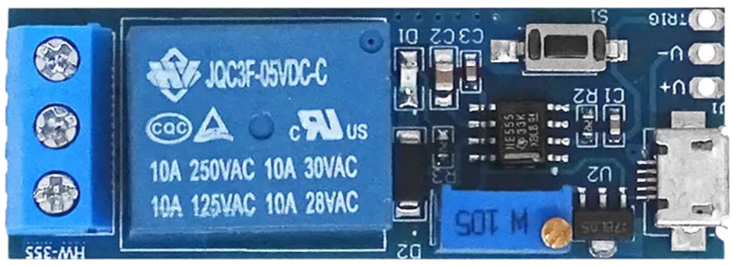
The Trigger Delay Relay 6-30V is a versatile electronic component designed to activate a relay after a user-defined delay when triggered. Operating within a voltage range of 6 to 30 volts, this relay module is ideal for timing applications in various circuits. It is commonly used in automation systems, DIY electronics projects, and industrial control systems where precise timing is required.
Explore Projects Built with Trigger Delay Relay 6-30V


Explore Projects Built with Trigger Delay Relay 6-30V
Common Applications and Use Cases
- Automation Systems: Delayed activation of motors, lights, or other devices.
- DIY Electronics Projects: Creating timed circuits for hobbyist applications.
- Industrial Control: Sequential activation of machinery or processes.
- Security Systems: Delayed triggering of alarms or locks.
- Home Automation: Timed control of appliances or lighting systems.
Technical Specifications
Below are the key technical details and pin configurations for the Trigger Delay Relay 6-30V module:
Key Technical Details
| Parameter | Specification |
|---|---|
| Operating Voltage | 6V to 30V DC |
| Trigger Voltage | 3.3V to 24V DC |
| Relay Output Type | Normally Open (NO) and Normally Closed (NC) |
| Maximum Load Current | 10A @ 250V AC or 10A @ 30V DC |
| Delay Time Range | 0.1 seconds to 999 seconds |
| Trigger Modes | High-level trigger or low-level trigger |
| Power Consumption | < 0.5W |
| Dimensions | ~50mm x 26mm x 18mm |
Pin Configuration and Descriptions
| Pin Name | Description |
|---|---|
| VCC | Positive power supply input (6V to 30V DC). |
| GND | Ground connection for the power supply. |
| IN | Trigger input pin (accepts 3.3V to 24V DC). |
| NO (Normally Open) | Relay output pin that remains open until the relay is activated. |
| NC (Normally Closed) | Relay output pin that remains closed until the relay is activated. |
| COM | Common pin for the relay output. |
Usage Instructions
How to Use the Component in a Circuit
- Power the Module: Connect the VCC pin to a DC power source (6V to 30V) and the GND pin to ground.
- Set the Delay Time: Use the onboard potentiometer or buttons (if available) to adjust the delay time. Refer to the module's markings or manual for specific adjustment instructions.
- Connect the Trigger Input: Attach the IN pin to a trigger signal source (e.g., a microcontroller, switch, or sensor). Ensure the trigger voltage is within the range of 3.3V to 24V DC.
- Connect the Load: Wire the load to the relay output pins (NO, NC, and COM) based on your desired configuration:
- Use NO and COM for a circuit that activates after the delay.
- Use NC and COM for a circuit that deactivates after the delay.
- Test the Circuit: Apply the trigger signal and observe the relay's behavior. The relay will activate after the specified delay.
Important Considerations and Best Practices
- Voltage Compatibility: Ensure the power supply voltage is within the 6V to 30V range to avoid damage to the module.
- Trigger Signal: Verify that the trigger signal voltage is between 3.3V and 24V DC.
- Load Ratings: Do not exceed the relay's maximum load current (10A @ 250V AC or 10A @ 30V DC).
- Isolation: Use optocouplers or other isolation techniques if the relay is connected to high-voltage circuits.
- Debouncing: If using a mechanical switch as the trigger, consider adding a debounce circuit to prevent false triggering.
Example: Using with an Arduino UNO
Below is an example of how to use the Trigger Delay Relay 6-30V with an Arduino UNO to control a light after a delay:
// Example: Trigger Delay Relay with Arduino UNO
// This code triggers the relay after a 5-second delay when a button is pressed.

const int triggerPin = 7;  // Pin connected to the relay's IN pin
const int buttonPin = 2;   // Pin connected to the button
int buttonState = 0;       // Variable to store the button state

void setup() {
  pinMode(triggerPin, OUTPUT);  // Set the relay pin as an output
  pinMode(buttonPin, INPUT_PULLUP);  // Set the button pin as an input with pull-up
  digitalWrite(triggerPin, LOW);  // Ensure the relay is off initially
}

void loop() {
  buttonState = digitalRead(buttonPin);  // Read the button state

  if (buttonState == LOW) {  // Check if the button is pressed
    delay(5000);  // Wait for 5 seconds (delay time)
    digitalWrite(triggerPin, HIGH);  // Activate the relay
    delay(1000);  // Keep the relay on for 1 second
    digitalWrite(triggerPin, LOW);  // Deactivate the relay
  }
}
Troubleshooting and FAQs
Common Issues and Solutions
Relay Does Not Activate
- Cause: Insufficient power supply voltage or current.
- Solution: Verify that the power supply provides 6V to 30V DC and sufficient current.
Incorrect Delay Time
- Cause: Misconfigured delay settings.
- Solution: Adjust the potentiometer or buttons to set the correct delay time.
Trigger Signal Not Detected
- Cause: Trigger voltage is outside the acceptable range.
- Solution: Ensure the trigger signal voltage is between 3.3V and 24V DC.
Load Not Functioning Properly
- Cause: Incorrect wiring of the relay output pins.
- Solution: Double-check the connections to the NO, NC, and COM pins.
FAQs
Q: Can I use this relay with an AC load?
A: Yes, the relay supports AC loads up to 250V at 10A. Ensure proper isolation and safety precautions.
Q: How do I reset the delay time?
A: Adjust the onboard potentiometer or buttons to reset the delay time. Refer to the module's manual for detailed instructions.
Q: Can I use this relay with a Raspberry Pi?
A: Yes, the relay can be triggered by a Raspberry Pi GPIO pin. Use a 3.3V logic level for the trigger input.
Q: Is the relay suitable for inductive loads?
A: Yes, but it is recommended to use a flyback diode or snubber circuit to protect the relay from voltage spikes.