How to Use 12v Relay: Examples, Pinouts, and Specs
Introduction
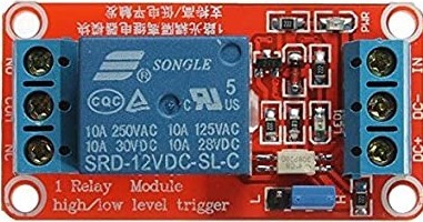
A 12V relay is an electromechanical switch that allows a low-power electrical signal to control a much higher power circuit. It is a critical component in various applications, including automotive electronics, home automation, and industrial control systems. Relays are used to switch on/off lights, motors, and other high-power devices, providing isolation between the control circuit and the power circuit.
Explore Projects Built with 12v Relay


Explore Projects Built with 12v Relay
Technical Specifications
Key Technical Details
- Coil Voltage: 12V DC
- Contact Capacity: Typically 10A @ 250V AC or 10A @ 30V DC
- Switching Voltage: Maximum 250V AC or 30V DC
- Operate Time: Typically 10ms or less
- Release Time: Typically 5ms or less
- Electrical Life: 100,000 operations
- Mechanical Life: 10,000,000 operations
Pin Configuration and Descriptions
| Pin Number | Description | Notes |
|---|---|---|
| 1 | Coil End 1 | Connect to 12V power supply |
| 2 | Coil End 2 | Connect to ground through control |
| 3 | Common (COM) | Connect to the common line |
| 4 | Normally Open (NO) | Closed when relay is energized |
| 5 | Normally Closed (NC) | Open when relay is energized |
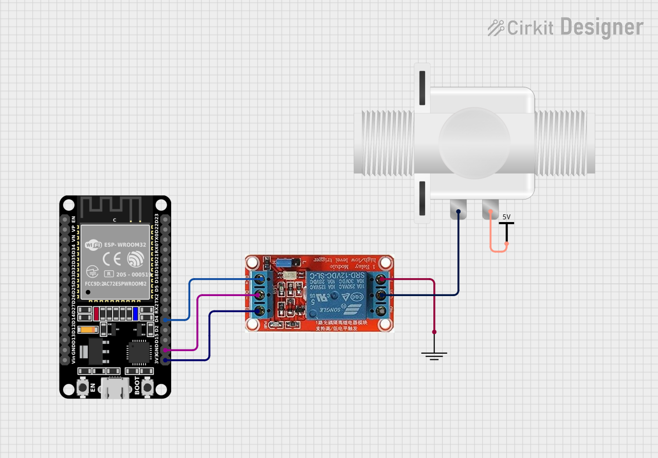
Usage Instructions
How to Use the Component in a Circuit
Powering the Coil:
- Connect pin 1 to a 12V power source.
- Connect pin 2 to the ground through a control signal (e.g., a microcontroller pin).
Switching a Load:
- Connect the common line of the load to the COM pin (3).
- Choose NO (4) or NC (5) based on whether the load should be powered when the relay is energized or de-energized, respectively.
Important Considerations and Best Practices
- Voltage Rating: Ensure the coil is powered with 12V; higher voltages may damage the relay.
- Current Rating: Do not exceed the contact capacity of the relay with the connected load.
- Flyback Diode: Always use a flyback diode across the relay coil to prevent back EMF damage when the coil is de-energized.
- Isolation: Maintain proper isolation between the low-power control circuit and the high-power load circuit.
Example Code for Arduino UNO
// Define relay control pin
const int relayPin = 2;

void setup() {
  // Set the relay pin as an output
  pinMode(relayPin, OUTPUT);
}

void loop() {
  // Turn on the relay (NO contact will close)
  digitalWrite(relayPin, HIGH);
  delay(1000); // Wait for 1 second

  // Turn off the relay (NO contact will open)
  digitalWrite(relayPin, LOW);
  delay(1000); // Wait for 1 second
}
Troubleshooting and FAQs
Common Issues
- Relay Does Not Actuate:
- Check if the coil is receiving 12V power.
- Verify the control signal is correctly connected and functioning.
- Load Does Not Power On/Off:
- Ensure the load is correctly connected to the COM and either NO or NC terminals.
- Check if the load exceeds the relay's contact capacity.
Solutions and Tips for Troubleshooting
- Check Connections: Double-check all wiring and solder joints.
- Test Coil: Use a multimeter to verify the coil is receiving the correct voltage.
- Control Signal: Ensure the control signal from the microcontroller is reaching the relay.
- Flyback Diode: Confirm that a flyback diode is in place to protect against voltage spikes.
FAQs
Q: Can I use the relay with AC loads? A: Yes, the relay can switch AC loads up to its rated voltage and current.
Q: How do I know if the relay is working? A: You should hear a clicking sound when the relay actuates. You can also use a multimeter to test continuity across the NO or NC contacts when the relay is energized or de-energized.
Q: Is it safe to switch high-power loads with a relay? A: Yes, as long as the load does not exceed the relay's rated capacity and proper precautions are taken for isolation and protection.
Remember to always follow safety guidelines when working with high voltage and current to prevent accidents and equipment damage.