
Cirkit Designer
Your all-in-one circuit design IDE
Home /
Component Documentation
How to Use TVS: Examples, Pinouts, and Specs

 Design with TVS in Cirkit Designer
Introduction
- A Transient Voltage Suppressor (TVS) is a protective electronic component designed to safeguard sensitive circuits from voltage spikes and transient surges. It operates by clamping excessive voltage to a safe level, thereby preventing damage to connected components.
- Common applications include:
- Protection of power supply lines in industrial and consumer electronics.
- Safeguarding data lines in communication systems.
- Automotive electronics to protect against load dump and ESD (Electrostatic Discharge).
- Circuit protection in LED lighting systems and medical devices.
Explore Projects Built with TVS
NodeMCU ESP8266 Controlled Drone with TFT Display and nRF24L01 Communication
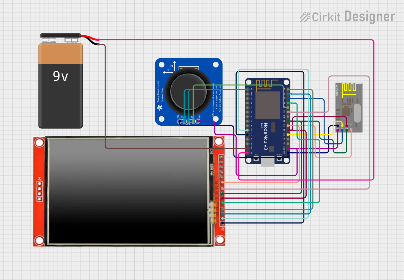
This circuit features a NodeMCU V3 ESP8266 microcontroller interfaced with an LCD TFT screen, an nRF24L01 wireless transceiver, and an Adafruit Analog 2-Axis Joystick. The NodeMCU collects joystick inputs and displays information on the TFT screen, while also communicating with other devices via the nRF24L01 module. The circuit is powered by a 9V battery, with the NodeMCU regulating the voltage for other components.
Open Project in Cirkit DesignerESP32-Based Smart Environmental Control System with PIR and Temperature Sensing
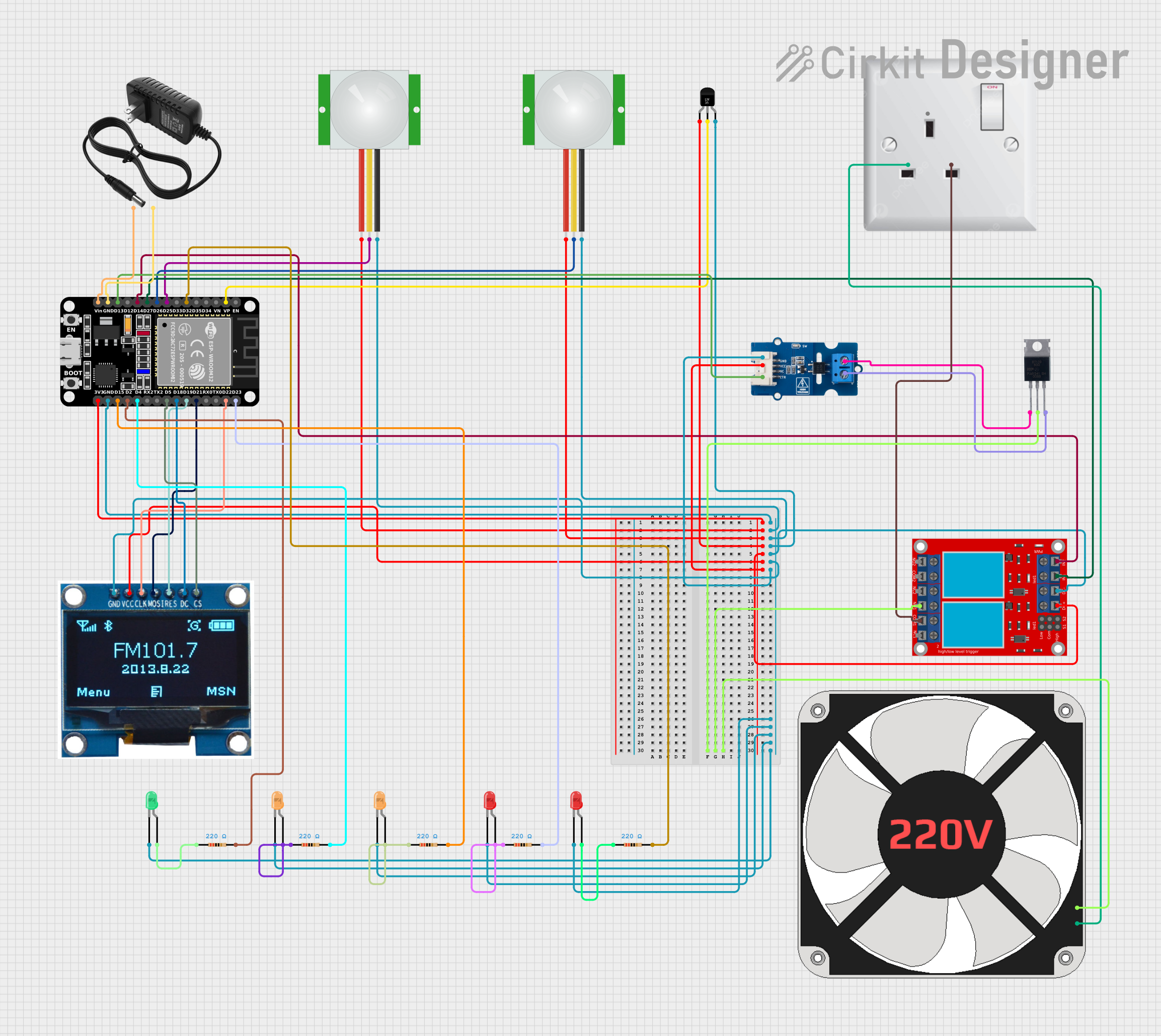
This circuit is a smart control system featuring an ESP32 microcontroller that processes inputs from PIR motion sensors and a temperature sensor, displays data on an OLED screen, and controls a 220V fan using a relay and triac. It includes status indication through LEDs and is powered by a 12V supply, with the ESP32 regulated to 3.3V.
Open Project in Cirkit DesignerNodeMCU ESP8266 Controlled Servo with IR Sensors
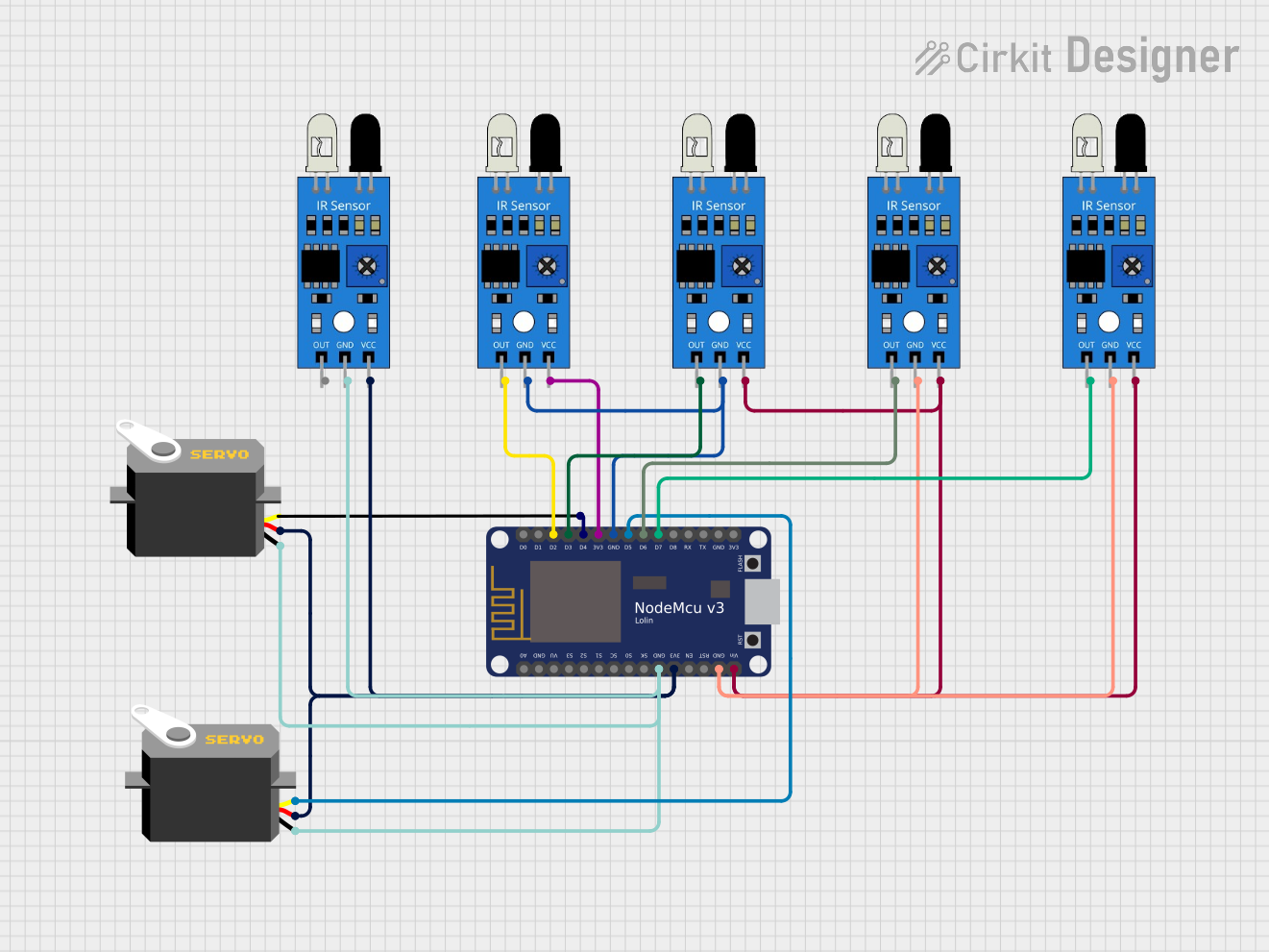
This circuit features a NodeMCU V3 ESP8266 microcontroller connected to multiple IR sensors and servo motors. The IR sensors are interfaced with the NodeMCU's digital pins and are likely used to detect objects or motion. The servo motors are controlled by the NodeMCU through PWM signals, enabling precise angular positioning based on the input from the IR sensors.
Open Project in Cirkit DesignerESP32 and TEA5767 FM Radio with ILI9341 Display and Potentiometer Tuning
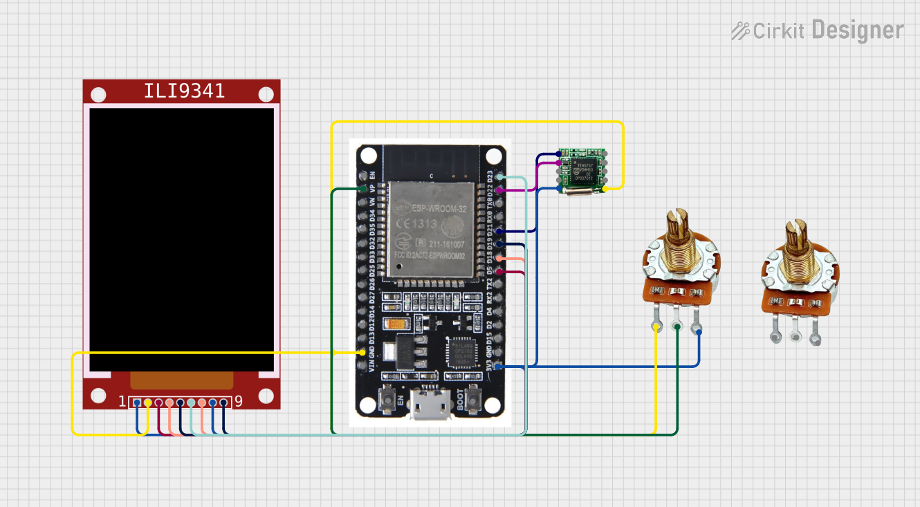
This circuit is an FM radio receiver with a TEA5767 tuner module controlled by an ESP32 microcontroller. The ESP32 reads the frequency input from a rotary potentiometer and displays the current frequency on an ILI9341 TFT display. The microcontroller adjusts the tuner frequency via I2C communication based on the potentiometer's position.
Open Project in Cirkit DesignerExplore Projects Built with TVS
NodeMCU ESP8266 Controlled Drone with TFT Display and nRF24L01 Communication
This circuit features a NodeMCU V3 ESP8266 microcontroller interfaced with an LCD TFT screen, an nRF24L01 wireless transceiver, and an Adafruit Analog 2-Axis Joystick. The NodeMCU collects joystick inputs and displays information on the TFT screen, while also communicating with other devices via the nRF24L01 module. The circuit is powered by a 9V battery, with the NodeMCU regulating the voltage for other components.
Open Project in Cirkit DesignerESP32-Based Smart Environmental Control System with PIR and Temperature Sensing
This circuit is a smart control system featuring an ESP32 microcontroller that processes inputs from PIR motion sensors and a temperature sensor, displays data on an OLED screen, and controls a 220V fan using a relay and triac. It includes status indication through LEDs and is powered by a 12V supply, with the ESP32 regulated to 3.3V.
Open Project in Cirkit DesignerNodeMCU ESP8266 Controlled Servo with IR Sensors
This circuit features a NodeMCU V3 ESP8266 microcontroller connected to multiple IR sensors and servo motors. The IR sensors are interfaced with the NodeMCU's digital pins and are likely used to detect objects or motion. The servo motors are controlled by the NodeMCU through PWM signals, enabling precise angular positioning based on the input from the IR sensors.
Open Project in Cirkit DesignerESP32 and TEA5767 FM Radio with ILI9341 Display and Potentiometer Tuning
This circuit is an FM radio receiver with a TEA5767 tuner module controlled by an ESP32 microcontroller. The ESP32 reads the frequency input from a rotary potentiometer and displays the current frequency on an ILI9341 TFT display. The microcontroller adjusts the tuner frequency via I2C communication based on the potentiometer's position.
Open Project in Cirkit DesignerTechnical Specifications
Key Technical Details:
- Voltage Range: Typically 5V to 600V (depending on the TVS model).
- Power Dissipation: Commonly ranges from 400W to 30kW (peak pulse power).
- Response Time: Less than 1 picosecond for clamping action.
- Polarity: Available in unidirectional and bidirectional configurations.
- Package Types: DO-214, SOD-123, SMA, SMB, and others.
Pin Configuration and Descriptions:
- TVS diodes are typically two-terminal devices. Below is a general pin configuration:
| Pin Number | Pin Name | Description |
|---|---|---|
| 1 | Anode (+) | Positive terminal for unidirectional TVS or one terminal for bidirectional TVS. |
| 2 | Cathode (-) | Negative terminal for unidirectional TVS or the other terminal for bidirectional TVS. |
Usage Instructions
How to Use the Component in a Circuit:
- Determine the Voltage Rating: Select a TVS diode with a breakdown voltage slightly higher than the normal operating voltage of your circuit.
- Placement: Connect the TVS diode across the circuit to be protected. For unidirectional TVS, ensure the cathode is connected to the positive voltage line and the anode to the ground. For bidirectional TVS, polarity does not matter.
- Power Dissipation: Ensure the TVS diode's power rating is sufficient to handle the expected surge energy.
Important Considerations and Best Practices:
- Always verify the TVS diode's clamping voltage to ensure it does not interfere with normal circuit operation.
- Use TVS diodes with low leakage current to minimize power loss in low-power applications.
- For high-speed data lines, select TVS diodes with low capacitance to avoid signal distortion.
- Place the TVS diode as close as possible to the component or circuit being protected to minimize inductive effects.
Example: Connecting a TVS Diode to an Arduino UNO: Below is an example of using a TVS diode to protect the Arduino UNO's 5V power supply line:
/*
  Example: Using a TVS diode to protect the Arduino UNO's 5V line.
  - TVS diode: SMAJ5.0A (5V unidirectional TVS diode)
  - The TVS diode is connected across the 5V and GND pins of the Arduino UNO.
*/

// No specific code is required for the TVS diode itself, as it operates passively.
// Ensure the SMAJ5.0A cathode is connected to the 5V pin and the anode to the GND pin.
Troubleshooting and FAQs
Common Issues Users Might Face:
- TVS Diode Overheating:
- Cause: The diode is exposed to surges beyond its power rating.
- Solution: Use a TVS diode with a higher power dissipation rating.
- Circuit Malfunction Due to Incorrect Voltage Rating:
- Cause: The TVS diode's breakdown voltage is too low, causing it to clamp during normal operation.
- Solution: Select a TVS diode with a breakdown voltage slightly above the circuit's operating voltage.
- Signal Distortion in High-Speed Data Lines:
- Cause: High capacitance of the TVS diode.
- Solution: Use a low-capacitance TVS diode designed for high-speed applications.
- TVS Diode Overheating:
FAQs:
- Can I use a bidirectional TVS diode in place of a unidirectional one?
- Yes, but only if the circuit does not require polarity-specific protection.
- How do I test if a TVS diode is functioning correctly?
- Use a multimeter in diode mode. For unidirectional TVS, check the forward voltage drop (similar to a standard diode). For bidirectional TVS, test in both directions.
- What happens if I exceed the TVS diode's power rating?
- The diode may fail permanently, potentially shorting or becoming open-circuit. Always choose a diode with a sufficient safety margin for power dissipation.
- Can I use a bidirectional TVS diode in place of a unidirectional one?