How to Use MD145SW-DroneCAN: Examples, Pinouts, and Specs
Introduction
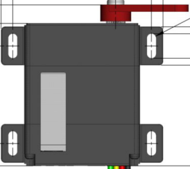
The MD145SW-DroneCAN Servo by Hitec is a high-performance servo motor integrated with the DroneCAN communication protocol. Designed specifically for drone and UAV applications, this servo enables seamless and reliable communication over the CAN (Controller Area Network) bus. Its robust design and precise control make it ideal for applications requiring high reliability, such as drone flight control, gimbal stabilization, and robotic systems.
Explore Projects Built with MD145SW-DroneCAN

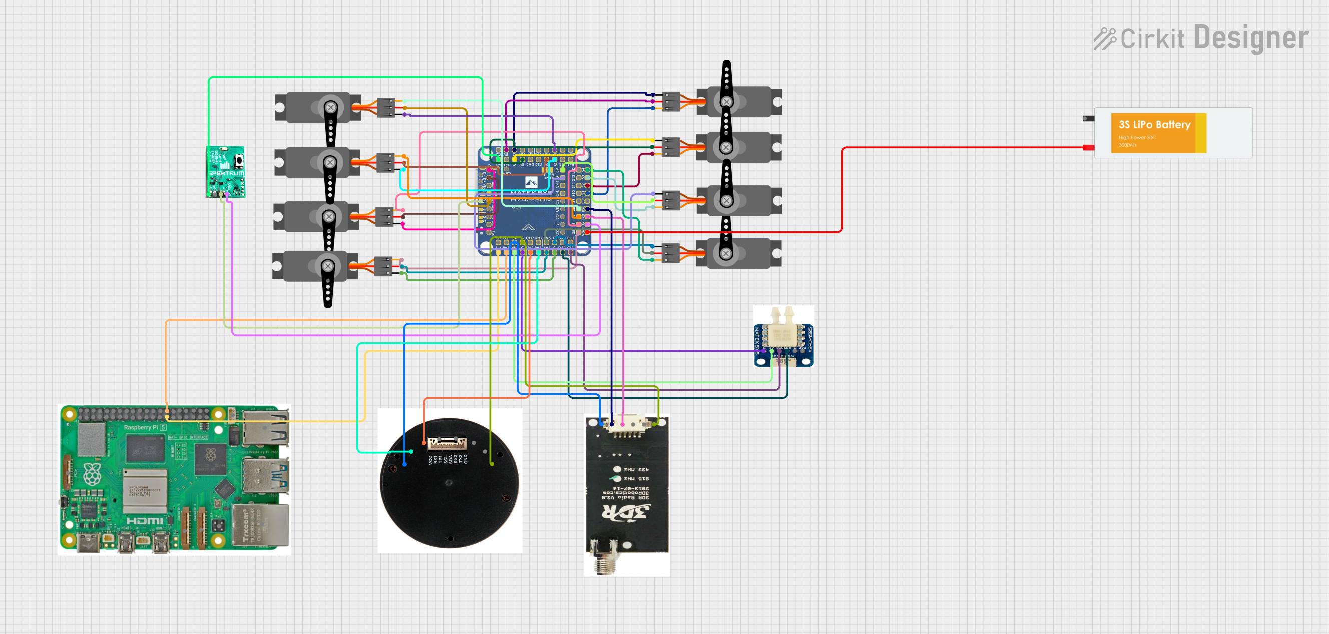
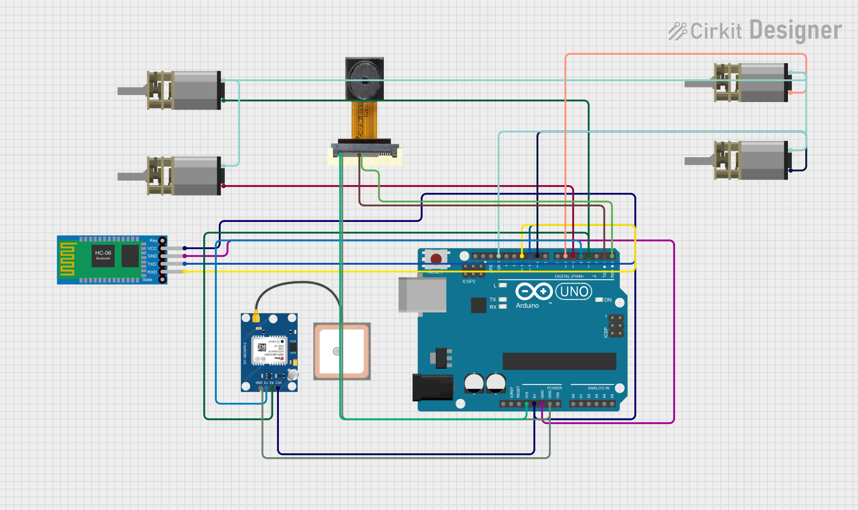
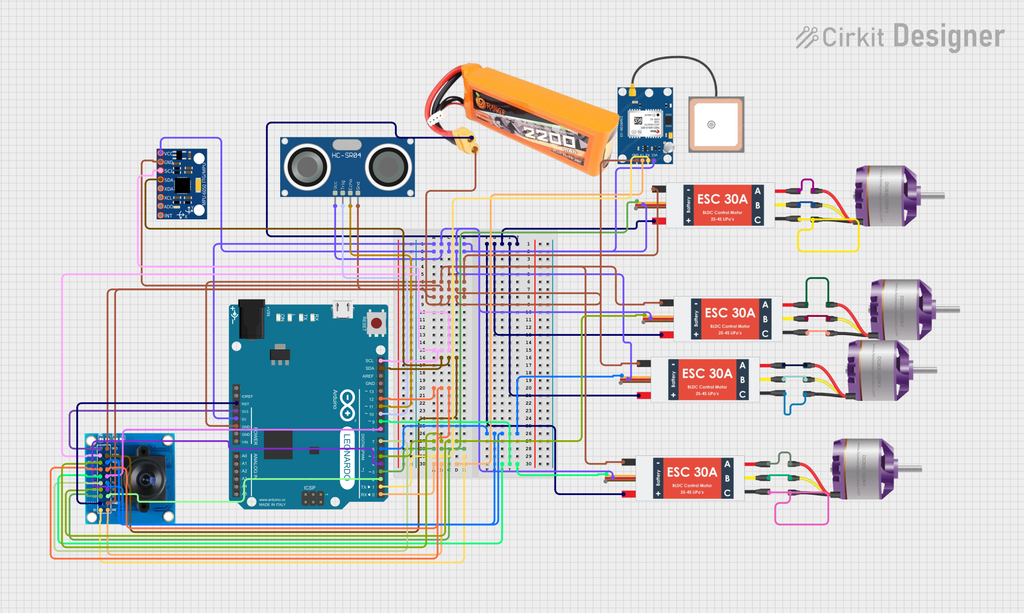
Explore Projects Built with MD145SW-DroneCAN
Common Applications and Use Cases
- Drone flight control systems
- Gimbal stabilization for cameras
- Robotic arms and manipulators
- UAV payload management
- Autonomous vehicle systems
Technical Specifications
Key Technical Details
| Parameter | Value |
|---|---|
| Manufacturer | Hitec |
| Part ID | MD145SW-DroneCAN Servo |
| Communication Protocol | DroneCAN (based on CAN bus) |
| Operating Voltage Range | 4.8V - 8.4V |
| Maximum Torque | 15 kg·cm @ 7.4V |
| Operating Speed | 0.12 sec/60° @ 7.4V |
| Operating Temperature | -20°C to 60°C |
| Dimensions | 40.5mm x 20mm x 38mm |
| Weight | 60g |
| Connector Type | Standard 3-pin servo connector |
| Data Rate | Up to 1 Mbps (CAN bus) |
Pin Configuration and Descriptions
| Pin Number | Pin Name | Description |
|---|---|---|
| 1 | VCC | Power supply input (4.8V - 8.4V) |
| 2 | GND | Ground connection |
| 3 | CAN_H | CAN bus high signal |
| 4 | CAN_L | CAN bus low signal |
Usage Instructions
How to Use the MD145SW-DroneCAN Servo in a Circuit
- Power Supply: Connect the servo's VCC pin to a regulated power source within the range of 4.8V to 8.4V. Ensure the power source can supply sufficient current for the servo's operation.
- Ground Connection: Connect the GND pin to the ground of your circuit.
- CAN Bus Connection:
- Connect the
CAN_HandCAN_Lpins to the corresponding CAN bus lines in your system. - Ensure proper termination resistors (typically 120Ω) are present at both ends of the CAN bus.
- Connect the
- Initialization: Configure your DroneCAN-compatible controller or flight controller to recognize and communicate with the servo. Use the appropriate DroneCAN node ID for the servo.
Important Considerations and Best Practices
- Power Supply: Use a stable and noise-free power source to avoid erratic behavior.
- CAN Bus Termination: Ensure proper termination resistors are in place to maintain signal integrity on the CAN bus.
- Node ID Configuration: Assign a unique DroneCAN node ID to the servo to avoid conflicts with other devices on the network.
- Firmware Updates: Check for firmware updates from Hitec to ensure compatibility with the latest DroneCAN features.
- Mechanical Mounting: Securely mount the servo to prevent vibrations or mechanical stress during operation.
Example Code for Arduino UNO with DroneCAN
Below is an example of how to control the MD145SW-DroneCAN Servo using an Arduino UNO with a CAN bus shield:
#include <mcp_can.h>
#include <SPI.h>

// Define CAN bus pins for the Arduino UNO
#define CAN_CS_PIN 10
#define CAN_INT_PIN 2

MCP_CAN CAN(CAN_CS_PIN); // Initialize CAN bus object

void setup() {
  Serial.begin(115200);
  while (!Serial);

  // Initialize CAN bus at 500 kbps
  if (CAN.begin(MCP_ANY, 500000, MCP_8MHZ) == CAN_OK) {
    Serial.println("CAN bus initialized successfully!");
  } else {
    Serial.println("CAN bus initialization failed!");
    while (1);
  }

  CAN.setMode(MCP_NORMAL); // Set CAN bus to normal mode
  Serial.println("CAN bus set to normal mode.");
}

void loop() {
  // Example: Send a command to set servo position
  byte servoCommand[8] = {0x01, 0x00, 0x00, 0x00, 0x00, 0x00, 0x00, 0x00};
  // 0x01: Command ID for position control
  // Remaining bytes: Position data (customize as per your application)

  if (CAN.sendMsgBuf(0x100, 0, 8, servoCommand) == CAN_OK) {
    Serial.println("Servo command sent successfully!");
  } else {
    Serial.println("Failed to send servo command.");
  }

  delay(1000); // Wait 1 second before sending the next command
}
Notes:
- Replace
0x100with the appropriate CAN ID for your servo. - Modify the
servoCommandarray to send specific position or control data.
Troubleshooting and FAQs
Common Issues and Solutions
Servo Not Responding:
- Ensure the power supply voltage is within the specified range (4.8V - 8.4V).
- Verify the CAN bus connections (
CAN_HandCAN_L) and ensure proper termination resistors are in place. - Check that the DroneCAN node ID is correctly configured and does not conflict with other devices.
Erratic Behavior:
- Check for noise or instability in the power supply.
- Ensure the CAN bus wiring is properly shielded and not excessively long.
Communication Errors:
- Verify the CAN bus baud rate matches the servo's configuration (default: 500 kbps).
- Inspect the CAN bus for loose or damaged connections.
FAQs
Q: Can I use the MD145SW-DroneCAN Servo with a non-DroneCAN controller?
A: No, the servo is specifically designed for DroneCAN-compatible systems. It requires a CAN bus interface for communication.
Q: What is the maximum cable length for the CAN bus?
A: The maximum length depends on the baud rate. For 500 kbps, the recommended maximum length is approximately 100 meters.
Q: How do I update the servo firmware?
A: Firmware updates can be performed using a DroneCAN-compatible tool or software provided by Hitec. Refer to the manufacturer's documentation for detailed instructions.
Q: Can I daisy-chain multiple servos on the same CAN bus?
A: Yes, multiple servos can be connected to the same CAN bus. Ensure each servo has a unique DroneCAN node ID.