How to Use PCF8574T IO Expansion Board: Examples, Pinouts, and Specs
Introduction
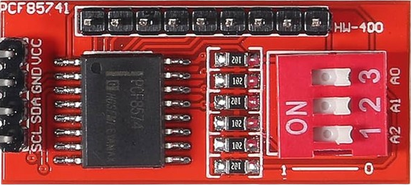
The PCF8574T IO Expansion Board by HiLetgo is an I2C-based I/O port expander that provides 8 additional digital input/output pins for microcontrollers. It is designed to simplify projects requiring more GPIO pins than are available on the main microcontroller. By utilizing the I2C communication protocol, the PCF8574T allows multiple devices to share the same bus, reducing wiring complexity.
Explore Projects Built with PCF8574T IO Expansion Board


Explore Projects Built with PCF8574T IO Expansion Board
Common Applications and Use Cases
- Expanding GPIO pins for microcontrollers like Arduino, ESP32, or Raspberry Pi.
- Controlling LEDs, relays, or other digital devices.
- Reading multiple button inputs or sensors.
- Building keypad interfaces or matrix displays.
- Projects requiring multiple I2C devices on a single bus.
Technical Specifications
The following are the key technical details of the PCF8574T IO Expansion Board:
| Parameter | Value |
|---|---|
| Operating Voltage | 2.5V to 6V |
| Communication Protocol | I2C (Inter-Integrated Circuit) |
| I2C Address Range | 0x20 to 0x27 (configurable via address pins) |
| Number of I/O Pins | 8 (P0 to P7) |
| Maximum Sink Current | 25mA per pin |
| Maximum Source Current | 300µA per pin |
| Operating Temperature | -40°C to +85°C |
Pin Configuration and Descriptions
The PCF8574T has 16 pins, as described in the table below:
| Pin | Name | Description |
|---|---|---|
| 1 | A0 | I2C address selection bit 0 (connect to GND or VCC to set address) |
| 2 | A1 | I2C address selection bit 1 (connect to GND or VCC to set address) |
| 3 | A2 | I2C address selection bit 2 (connect to GND or VCC to set address) |
| 4 | GND | Ground (0V reference) |
| 5 | SDA | I2C data line (connect to microcontroller SDA pin) |
| 6 | SCL | I2C clock line (connect to microcontroller SCL pin) |
| 7 | INT | Interrupt output (active low, optional for detecting pin state changes) |
| 8 | VCC | Power supply (2.5V to 6V) |
| 9-16 | P0 to P7 | General-purpose I/O pins (can be configured as input or output) |
Usage Instructions
How to Use the PCF8574T in a Circuit
Connect Power and Ground:
- Connect the
VCCpin to the power supply (e.g., 5V for Arduino). - Connect the
GNDpin to the ground of the microcontroller.
- Connect the
Set the I2C Address:
- Use the
A0,A1, andA2pins to configure the I2C address. - Each pin can be connected to
GND(logic 0) orVCC(logic 1), allowing up to 8 unique addresses (0x20 to 0x27).
- Use the
Connect I2C Lines:
- Connect the
SDApin to the microcontroller's SDA pin. - Connect the
SCLpin to the microcontroller's SCL pin. - Use pull-up resistors (typically 4.7kΩ) on the SDA and SCL lines if not already present.
- Connect the
Connect I/O Devices:
- Attach LEDs, buttons, or other devices to the
P0toP7pins. - Configure each pin as input or output in your code.
- Attach LEDs, buttons, or other devices to the
Important Considerations and Best Practices
- Pull-Up Resistors: Ensure proper pull-up resistors are used on the I2C lines if your microcontroller does not have internal pull-ups enabled.
- Current Limitations: Avoid exceeding the maximum sink/source current ratings to prevent damage to the chip.
- Interrupt Pin: Use the
INTpin if you need to detect changes on input pins without continuously polling.
Example Code for Arduino UNO
Below is an example of how to use the PCF8574T with an Arduino UNO to control LEDs and read button inputs:
#include <Wire.h> // Include the Wire library for I2C communication

#define PCF8574_ADDRESS 0x20 // Default I2C address of the PCF8574T

void setup() {
  Wire.begin(); // Initialize I2C communication
  Serial.begin(9600); // Start serial communication for debugging

  // Set all pins on the PCF8574T as outputs (write HIGH to turn off LEDs)
  Wire.beginTransmission(PCF8574_ADDRESS);
  Wire.write(0xFF); // All pins HIGH (default state for outputs)
  Wire.endTransmission();
}

void loop() {
  // Example: Toggle an LED connected to P0 every second
  Wire.beginTransmission(PCF8574_ADDRESS);
  Wire.write(0xFE); // Set P0 LOW (turn on LED), others HIGH
  Wire.endTransmission();
  delay(1000);

  Wire.beginTransmission(PCF8574_ADDRESS);
  Wire.write(0xFF); // Set all pins HIGH (turn off LED)
  Wire.endTransmission();
  delay(1000);
}
Notes:
- Replace
0x20with the actual I2C address if you have modified the address pins. - For input pins, read the state using
Wire.requestFrom()and process the returned byte.
Troubleshooting and FAQs
Common Issues and Solutions
I2C Communication Not Working:
- Ensure the SDA and SCL lines are correctly connected.
- Check for proper pull-up resistors on the I2C lines.
- Verify the I2C address matches the configuration of the
A0,A1, andA2pins.
Pins Not Responding:
- Confirm the pins are correctly configured as input or output in your code.
- Check for loose or incorrect wiring to the
P0toP7pins.
Interrupt Pin Not Triggering:
- Ensure the
INTpin is connected to a digital input pin on the microcontroller. - Verify that the input pins are configured to generate interrupts.
- Ensure the
FAQs
Q: Can I connect multiple PCF8574T boards to the same I2C bus?
A: Yes, you can connect up to 8 boards by configuring unique I2C addresses using the A0, A1, and A2 pins.
Q: What is the maximum cable length for I2C communication?
A: The maximum length depends on the pull-up resistor values and the speed of communication, but typically it is recommended to keep the length under 1 meter for reliable operation.
Q: Can the PCF8574T handle analog signals?
A: No, the PCF8574T is designed for digital input/output only. Use an ADC (Analog-to-Digital Converter) for analog signals.
Q: How do I know if the PCF8574T is working?
A: Use an I2C scanner sketch to detect the device on the bus. If detected, the PCF8574T is functioning correctly.