How to Use Adafruit MCP2221A USB to GPIO-I2C-ADC-DAC breakout: Examples, Pinouts, and Specs
Introduction
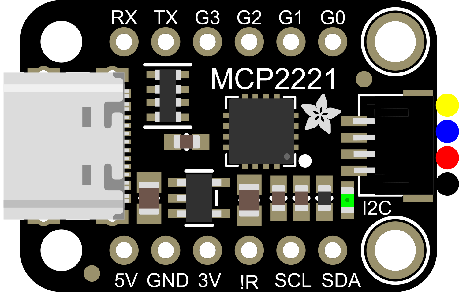
The Adafruit MCP2221A breakout board is a versatile and compact electronic component that bridges USB connectivity with various other common interfaces and functionalities. It serves as a USB to GPIO, I2C, ADC, and DAC converter, enabling communication between a computer and various external devices or sensors. This breakout is particularly useful for prototyping, testing, and integrating I2C devices, reading analog signals, controlling peripherals, and generating analog outputs without the need for a full microcontroller setup.
Explore Projects Built with Adafruit MCP2221A USB to GPIO-I2C-ADC-DAC breakout

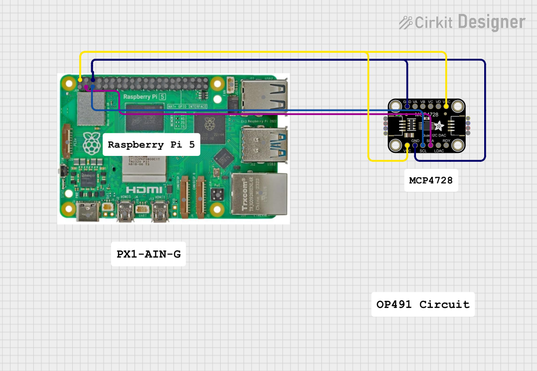

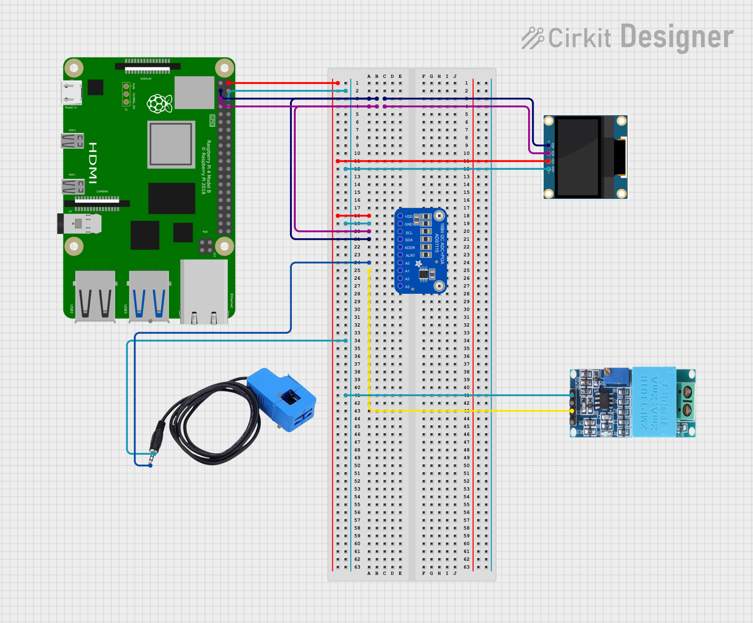
Explore Projects Built with Adafruit MCP2221A USB to GPIO-I2C-ADC-DAC breakout
Common Applications and Use Cases
- Rapid prototyping with I2C sensors
- USB interfacing for embedded systems
- Analog signal reading for data logging
- Generating analog voltages for testing purposes
- Controlling external devices via GPIO pins
Technical Specifications
Key Technical Details
- USB Interface: USB 2.0 Full Speed
- I2C Speed: Up to 400 kHz
- GPIO Pins: 4 (configurable as digital input or output)
- ADC Channels: 3 (10-bit resolution)
- DAC Channels: 1 (5-bit resolution)
- Operating Voltage: 3.3V
- Supply Current: 10 mA (typical)
Pin Configuration and Descriptions
| Pin Number | Name | Description |
|---|---|---|
| 1 | GP0 | Configurable as GPIO, ADC0, or DAC1 |
| 2 | GP1 | Configurable as GPIO or ADC1 |
| 3 | GP2 | Configurable as GPIO or ADC2 |
| 4 | GP3 | Configurable as GPIO or I2C SCL |
| 5 | SDA | I2C Data Line |
| 6 | VDD | 3.3V Power Supply Input |
| 7 | GND | Ground Connection |
| 8 | USB | USB Interface Connector |
Usage Instructions
How to Use the Component in a Circuit
Powering the Device:
- Connect the VDD pin to a 3.3V power supply.
- Ensure the GND pin is connected to the common ground of your system.
USB Communication:
- Connect the USB interface to a computer using a micro-USB cable.
- Install necessary drivers and Adafruit's MCP2221A library for communication.
I2C Communication:
- Connect SDA and SCL pins to your I2C device.
- Use the Adafruit MCP2221A library to initialize and communicate with I2C devices.
Using GPIO Pins:
- Configure the desired pins as input or output using the library functions.
- Read or write digital values to the GPIO pins as required.
Analog-to-Digital Conversion (ADC):
- Connect an analog signal to one of the ADC-capable GP pins.
- Use the library functions to read the analog value.
Digital-to-Analog Conversion (DAC):
- Configure GP0 as DAC output.
- Use the library functions to output an analog voltage.
Important Considerations and Best Practices
- Ensure that the power supply does not exceed 3.3V to avoid damaging the board.
- When using I2C, pull-up resistors may be necessary depending on your setup.
- Avoid applying voltages to the ADC pins that exceed the VDD pin voltage.
- The DAC output is limited in resolution and range; it is suitable for low-precision applications.
Troubleshooting and FAQs
Common Issues Users Might Face
- Device Not Recognized: Ensure that the drivers are installed correctly and the USB cable is functioning.
- I2C Communication Failure: Check for proper connections and pull-up resistors on the I2C lines.
- Inaccurate ADC Readings: Verify that the input voltage does not exceed the reference voltage and that the pin is configured correctly.
- Weak DAC Output: Remember that the DAC is 5-bit, which limits its resolution and output voltage range.
Solutions and Tips for Troubleshooting
- Always start by checking connections and ensuring that the power supply is within the specified range.
- Use the Adafruit MCP2221A library's example sketches to test each functionality separately.
- Consult the MCP2221A datasheet for detailed information on the chip's operation and limitations.
Example Code for Arduino UNO
Below is an example code snippet for initializing the I2C communication using the Adafruit MCP2221A with an Arduino UNO. Ensure you have installed the Adafruit MCP2221A library before uploading the code to the Arduino.
#include <Wire.h>
#include <Adafruit_MCP2221A.h>

// Initialize the MCP2221A
Adafruit_MCP2221A mcp;

void setup() {
  Serial.begin(9600);
  // Wait for serial port to open on native USB devices
  while (!Serial) {
    delay(1);
  }

  if (!mcp.begin()) {
    Serial.println("Failed to find MCP2221A chip");
    while (1) {
      delay(10);
    }
  }
  Serial.println("MCP2221A found!");

  // Set I2C speed
  mcp.setI2Cspeed(400000); // 400 KHz
  // Start I2C
  Wire.begin();
}

void loop() {
  // Your I2C communication code here
}
Remember to keep the code comments concise and within the 80 character line length limit. This example demonstrates how to initialize the MCP2221A and prepare it for I2C communication. Additional functionality such as GPIO control, ADC reading, and DAC output can be implemented using the library's functions and following the usage instructions provided above.