How to Use Raspberry Pi Pico: Examples, Pinouts, and Specs
Introduction
The Raspberry Pi Pico is a microcontroller board that marks the Raspberry Pi Foundation's entry into the microcontroller market. It is built around the RP2040, a dual-core ARM Cortex-M0+ processor designed by the Raspberry Pi Foundation. The Pico is designed for ease of use and accessibility, making it an excellent choice for both beginners and seasoned makers. It is suitable for a wide range of applications, from simple LED blink projects to complex IoT devices and embedded systems.
Explore Projects Built with Raspberry Pi Pico
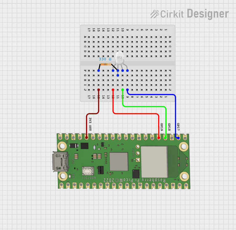
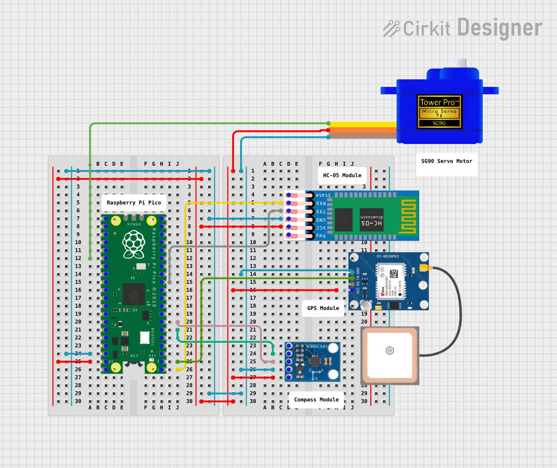

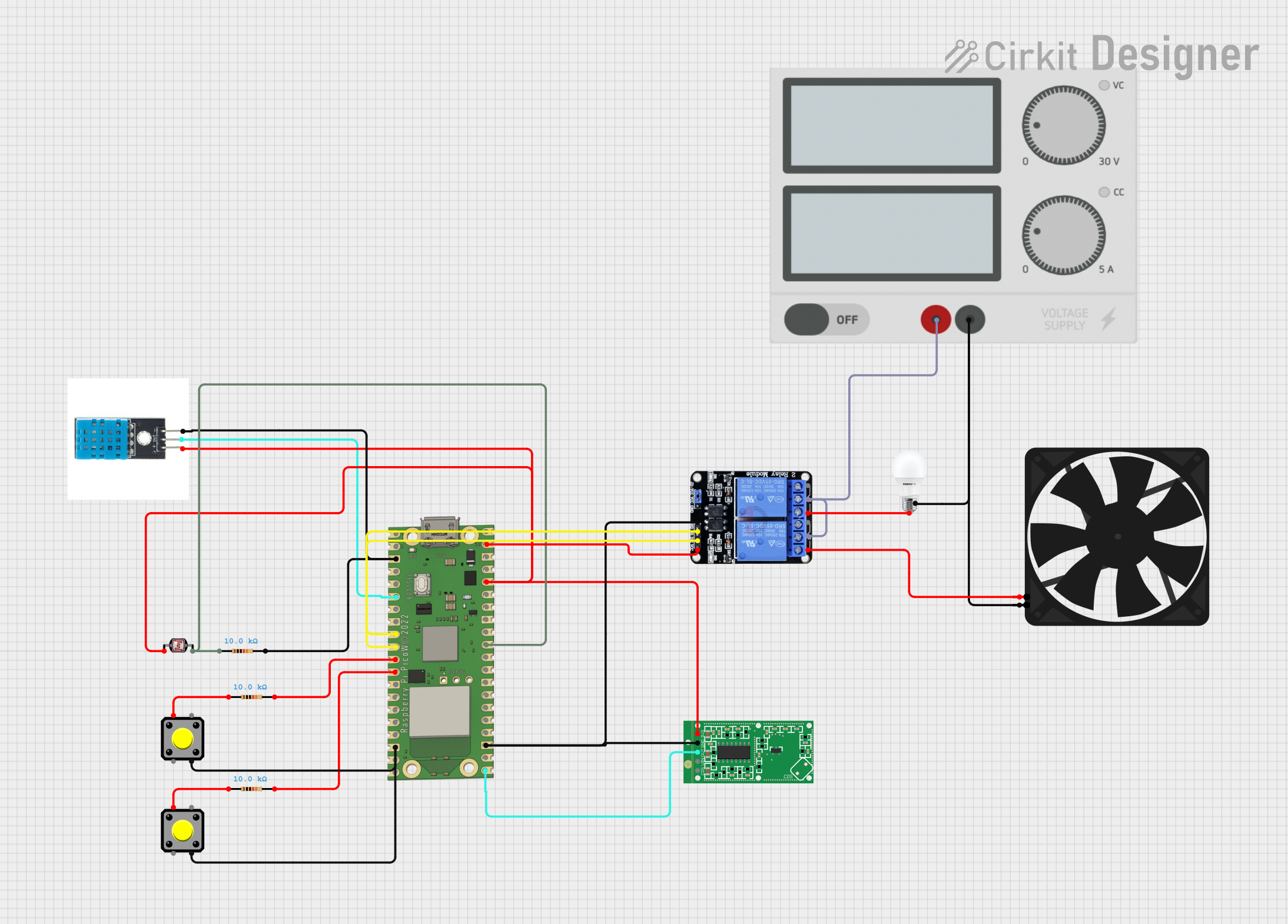
Explore Projects Built with Raspberry Pi Pico
Common Applications and Use Cases
- Educational projects and learning to program
- DIY electronics and hobbyist projects
- Prototyping IoT devices
- Wearable electronics
- Robotics
- Automation systems
Technical Specifications
Key Technical Details
- Chip: RP2040 microcontroller chip designed by Raspberry Pi in the United Kingdom
- Processor: Dual-core ARM Cortex-M0+ processor, flexible clock running up to 133 MHz
- Memory: 264KB of SRAM, and 2MB of on-board Flash memory
- GPIO: 26 multi-function GPIO pins
- Interfaces:
- 2 × SPI
- 2 × I2C
- 2 × UART
- 3 × 12-bit ADC
- 16 × controllable PWM channels
- Input Voltage: 1.8V to 5.5V
- Operating Temperature: -20°C to +85°C
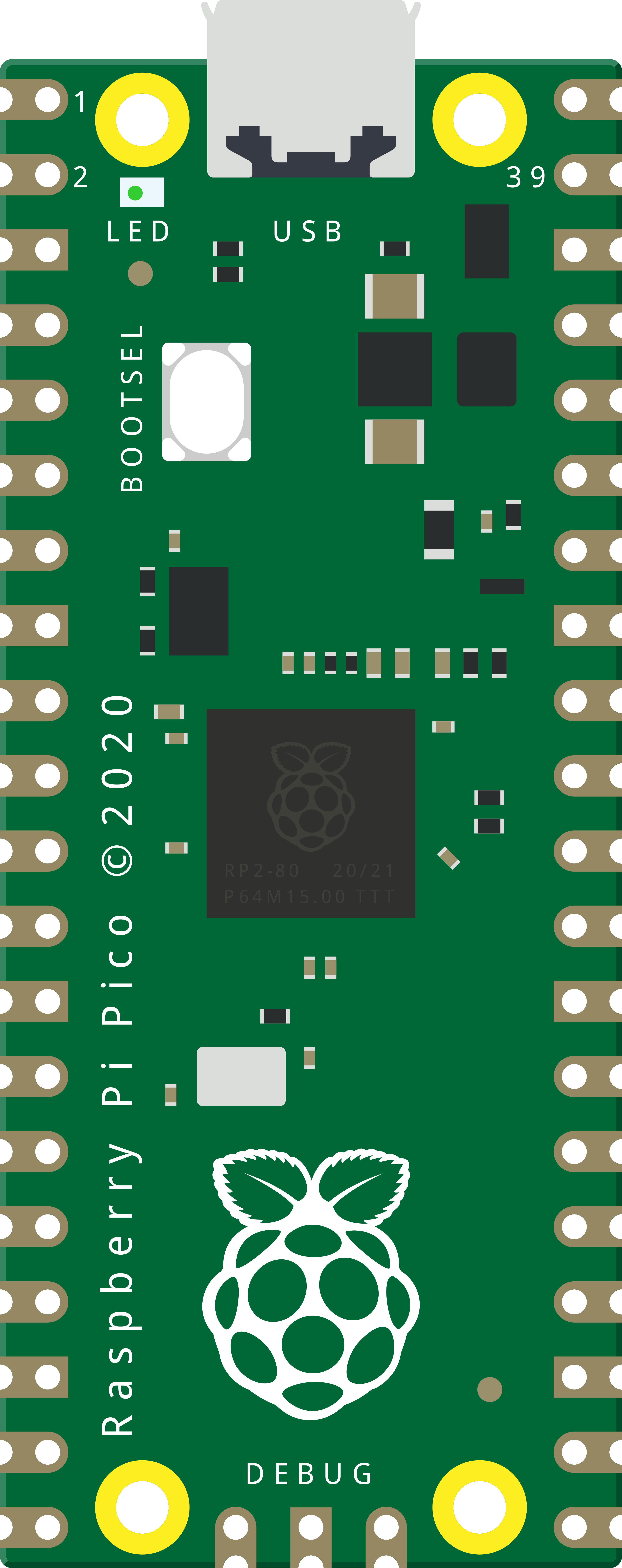
Pin Configuration and Descriptions
| Pin Number | Name | Function |
|---|---|---|
| 1 | VBUS | USB input voltage |
| 2 | VSYS | System input voltage |
| 3-6 | GND | Ground |
| 7 | GP0 | GPIO 0 / SPI RX |
| 8 | GP1 | GPIO 1 / SPI TX |
| ... | ... | ... |
| 40 | GP29 | GPIO 29 |
Note: This table is not exhaustive. Refer to the official datasheet for the full pinout.
Usage Instructions
How to Use the Component in a Circuit
- Powering the Pico: Connect the USB input (VBUS) to a 5V USB power source. Alternatively, you can supply voltage to the VSYS pin within the range of 1.8V to 5.5V.
- Connecting GPIO Pins: Use the GPIO pins for interfacing with sensors, actuators, and other components. Ensure that the voltage levels are compatible with the Pico's logic levels.
- Programming the Pico: Connect the Pico to a computer via a micro-USB cable. Use the Thonny IDE or another suitable development environment to write and upload code.
Important Considerations and Best Practices
- Always ensure that the power supply is within the specified range to avoid damaging the board.
- When interfacing with other components, check their voltage and current requirements to ensure compatibility.
- Use proper ESD precautions when handling the Pico to prevent static damage.
- To minimize noise and improve performance, use decoupling capacitors where necessary.
Troubleshooting and FAQs
Common Issues Users Might Face
- Pico Not Recognized by Computer: Ensure the micro-USB cable is properly connected and that it is a data cable capable of transferring data, not just charging.
- GPIO Pin Not Working: Check for proper pin initialization in your code and ensure there are no shorts or open circuits in your connections.
Solutions and Tips for Troubleshooting
- If the Pico is not recognized, try a different USB port or cable and ensure that your computer's OS has the necessary drivers installed.
- For GPIO issues, use a multimeter to check the continuity and voltage levels at the pin to diagnose the problem.
FAQs
Q: Can I use the Raspberry Pi Pico with Arduino IDE? A: Yes, the Pico can be programmed using the Arduino IDE with the appropriate board support package installed.
Q: What programming languages can I use with the Pico? A: The Pico supports C/C++ and MicroPython out of the box.
Q: How do I reset the Pico? A: You can reset the Pico by pressing and releasing the onboard RESET button.
Example Code for Arduino UNO
Here is an example of how to blink an LED connected to GPIO 15 on the Raspberry Pi Pico using MicroPython:
from machine import Pin, Timer
Initialize GPIO 15 as an output pin
led = Pin(15, Pin.OUT)
Toggle the LED state
def toggle_led(timer): led.toggle()
Create a software timer that toggles the LED every 500ms
timer = Timer() timer.init(freq=2, mode=Timer.PERIODIC, callback=toggle_led)
The LED will now toggle every 500ms
*Note: This code is written for MicroPython and is intended to be run on the Raspberry Pi Pico. The comments are wrapped to comply with the 80 character line length limit.*

For more detailed information, refer to the official Raspberry Pi Pico documentation and datasheets.