How to Use STM32F103C8T6(2): Examples, Pinouts, and Specs
Introduction
The STM32F103C8T6 is a 32-bit ARM Cortex-M3 microcontroller manufactured by STMicroelectronics. It features 64KB of flash memory and 20KB of SRAM, making it a versatile and high-performance solution for a wide range of embedded systems. This microcontroller is part of the STM32 family, known for its low power consumption, robust peripherals, and ease of integration.
Explore Projects Built with STM32F103C8T6(2)


Explore Projects Built with STM32F103C8T6(2)
Common Applications and Use Cases
- Industrial automation and control systems
- IoT devices and smart home applications
- Robotics and motor control
- Consumer electronics
- Data acquisition and signal processing
- Prototyping and development with platforms like Arduino or custom PCBs
Technical Specifications
The STM32F103C8T6 microcontroller offers the following key technical features:
| Parameter | Value |
|---|---|
| Core | ARM Cortex-M3, 32-bit RISC architecture |
| Operating Frequency | Up to 72 MHz |
| Flash Memory | 64 KB |
| SRAM | 20 KB |
| GPIO Pins | Up to 37 (multiplexed with other functions) |
| Communication Interfaces | USART, SPI, I2C, CAN, USB 2.0 FS |
| Timers | 3 general-purpose timers, 1 advanced-control timer, 2 watchdog timers |
| ADC | 12-bit, up to 16 channels |
| Operating Voltage | 2.0V to 3.6V |
| Power Consumption | Low-power modes available (down to 2 µA in standby mode) |
| Package | LQFP-48 (48-pin) |
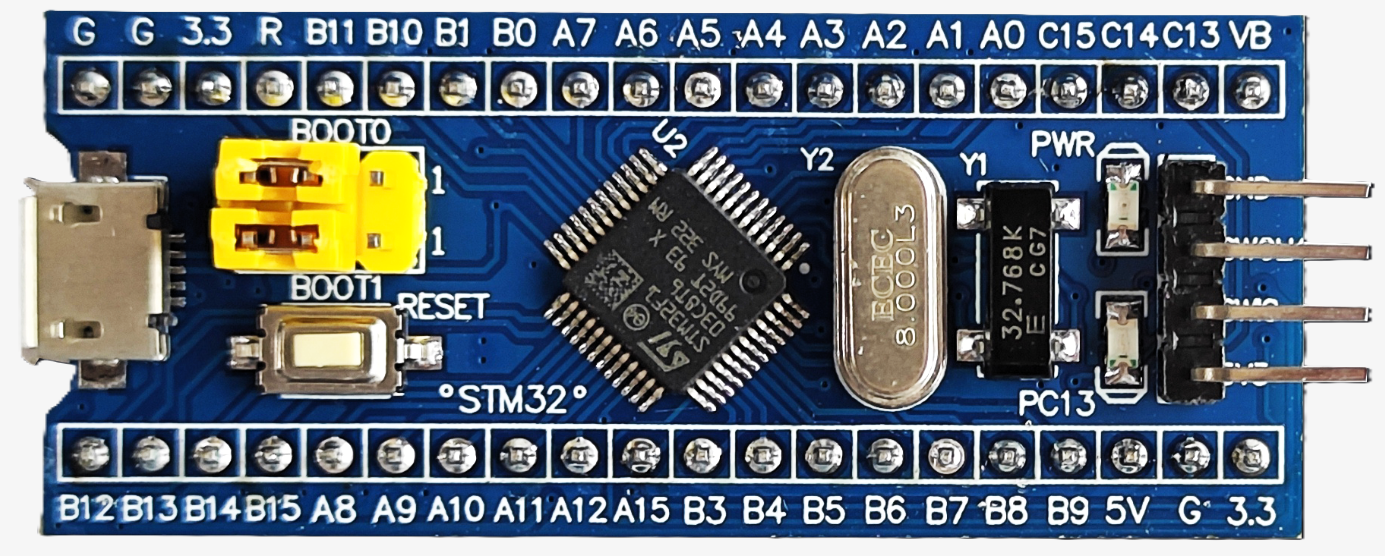
Pin Configuration and Descriptions
The STM32F103C8T6 has 48 pins, with the most commonly used pins described below:
| Pin Name | Pin Number | Function | Description |
|---|---|---|---|
| VDD | Multiple | Power Supply | 2.0V to 3.6V input |
| VSS | Multiple | Ground | Ground connection |
| PA0-PA15 | 10-25 | GPIO, ADC, USART, etc. | General-purpose I/O, multiplexed functions |
| PB0-PB15 | 26-41 | GPIO, SPI, I2C, etc. | General-purpose I/O, multiplexed functions |
| PC13-PC15 | 42-44 | GPIO | General-purpose I/O |
| NRST | 7 | Reset | Active-low reset input |
| OSC_IN | 5 | Oscillator Input | External clock input |
| OSC_OUT | 6 | Oscillator Output | External clock output |
| BOOT0 | 9 | Boot Mode Selection | Selects boot mode (Flash, RAM, or System) |
For a complete pinout, refer to the STM32F103C8T6 datasheet.
Usage Instructions
How to Use the STM32F103C8T6 in a Circuit
- Power Supply: Connect VDD to a 3.3V power source and VSS to ground. Ensure proper decoupling capacitors (e.g., 0.1 µF) are placed close to the VDD pins.
- Clock Configuration: Use an external 8 MHz crystal oscillator connected to OSC_IN and OSC_OUT, along with appropriate load capacitors (typically 22 pF).
- Boot Mode Selection: Use the BOOT0 pin to select the boot mode:
- Connect BOOT0 to GND for normal Flash memory boot.
- Connect BOOT0 to VDD for system memory boot (e.g., for firmware updates).
- Programming: Use an ST-Link programmer or USB-to-serial adapter to upload firmware via the SWD (Serial Wire Debug) interface or USART1.
- GPIO Configuration: Configure GPIO pins as input, output, or alternate function using the STM32 HAL (Hardware Abstraction Layer) or direct register programming.
Important Considerations and Best Practices
- Power Supply Stability: Ensure a stable 3.3V power supply with proper decoupling to avoid noise issues.
- Clock Source: For precise timing, use an external crystal oscillator. Internal RC oscillators are less accurate.
- Debugging: Use the SWD interface for debugging and firmware uploads.
- Peripheral Configuration: Use STM32CubeMX to generate initialization code for peripherals, reducing development time.
- Heat Dissipation: While the STM32F103C8T6 is efficient, ensure proper ventilation or heat sinking in high-performance applications.
Example Code for Arduino IDE
The STM32F103C8T6 can be programmed using the Arduino IDE with the STM32duino core. Below is an example of blinking an LED connected to pin PA5:
// Example: Blink an LED on PA5 using STM32F103C8T6
// Ensure STM32duino core is installed in Arduino IDE

#define LED_PIN PA5  // Define the LED pin (PA5)

void setup() {
  pinMode(LED_PIN, OUTPUT);  // Set PA5 as an output pin
}

void loop() {
  digitalWrite(LED_PIN, HIGH);  // Turn the LED on
  delay(1000);                  // Wait for 1 second
  digitalWrite(LED_PIN, LOW);   // Turn the LED off
  delay(1000);                  // Wait for 1 second
}
Troubleshooting and FAQs
Common Issues and Solutions
Microcontroller Not Responding
- Cause: Incorrect power supply or missing decoupling capacitors.
- Solution: Verify the power supply voltage (3.3V) and add decoupling capacitors near VDD pins.
Unable to Upload Code
- Cause: Incorrect BOOT0 pin configuration or faulty programmer connection.
- Solution: Ensure BOOT0 is set to GND for Flash memory boot. Check connections to the ST-Link or USB-to-serial adapter.
Clock Issues
- Cause: Improper external crystal oscillator setup.
- Solution: Verify the crystal oscillator frequency and load capacitor values.
GPIO Pins Not Working
- Cause: Incorrect pin configuration or peripheral conflict.
- Solution: Check the pin configuration in the code and ensure no conflicts with other peripherals.
FAQs
Q: Can I use the STM32F103C8T6 with 5V logic?
A: No, the STM32F103C8T6 operates at 3.3V. Use level shifters for interfacing with 5V logic.Q: How do I reset the microcontroller?
A: Use the NRST pin or software reset via the system control register.Q: What development tools are recommended?
A: STM32CubeIDE, Keil uVision, or Arduino IDE with STM32duino core.Q: Can I use the internal oscillator instead of an external crystal?
A: Yes, but the internal oscillator is less accurate and may not be suitable for timing-critical applications.