How to Use Limit Switch KW12-3: Examples, Pinouts, and Specs
Introduction
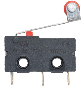
The Limit Switch KW12-3 is a mechanical switch designed to detect the presence or position of an object. It is commonly used in industrial automation systems, machinery, and safety applications. This compact and durable switch is ideal for controlling processes, ensuring safety, and providing feedback in automated systems. Its versatility and reliability make it a popular choice in both industrial and hobbyist projects.
Explore Projects Built with Limit Switch KW12-3


Explore Projects Built with Limit Switch KW12-3
Common Applications
- Detecting the position of moving parts in machinery
- Safety interlocks in industrial equipment
- End-stop detection in 3D printers and CNC machines
- Robotics and automation systems
- Home appliances and DIY electronics projects
Technical Specifications
The following table outlines the key technical details of the KW12-3 limit switch:
| Parameter | Specification |
|---|---|
| Operating Voltage | 125V AC / 250V AC |
| Rated Current | 5A |
| Contact Configuration | SPDT (Single Pole Double Throw) |
| Mechanical Life | 1,000,000 cycles |
| Electrical Life | 50,000 cycles |
| Operating Force | 50gf to 200gf |
| Operating Temperature | -25°C to +85°C |
| Dimensions | 27.8mm x 10.3mm x 15.9mm |
| Mounting Hole Size | 2.2mm diameter |
Pin Configuration and Descriptions
The KW12-3 limit switch has three terminals, as described in the table below:
| Pin | Label | Description |
|---|---|---|
| 1 | COM | Common terminal. This is the main input terminal for the switch. |
| 2 | NO | Normally Open terminal. This terminal is connected to COM when the switch is activated. |
| 3 | NC | Normally Closed terminal. This terminal is connected to COM when the switch is not activated. |
Usage Instructions
How to Use the KW12-3 in a Circuit
- Identify the Terminals: Locate the COM, NO, and NC terminals on the switch.
- Connect the Circuit:
- For a normally open configuration, connect the load between the COM and NO terminals. The circuit will close when the switch is activated.
- For a normally closed configuration, connect the load between the COM and NC terminals. The circuit will open when the switch is activated.
- Mount the Switch: Secure the switch using screws or adhesive, ensuring the actuator is positioned to detect the desired object or motion.
- Test the Switch: Verify the switch operation by manually pressing the actuator and observing the circuit behavior.
Important Considerations
- Voltage and Current Ratings: Ensure the connected load does not exceed the switch's rated voltage (125V/250V AC) and current (5A).
- Debouncing: When using the switch in digital circuits, implement debouncing techniques to avoid false triggering due to mechanical bounce.
- Environmental Conditions: Avoid exposing the switch to extreme temperatures, moisture, or corrosive environments beyond its specified limits.
Example: Connecting to an Arduino UNO
The KW12-3 can be used with an Arduino UNO to detect the position of an object. Below is an example circuit and code:
Circuit
- Connect the COM terminal of the switch to the GND pin of the Arduino.
- Connect the NO terminal of the switch to digital pin 2 on the Arduino.
- Use a pull-up resistor (10kΩ) between digital pin 2 and the 5V pin of the Arduino.
Code
// Example code for using the KW12-3 limit switch with Arduino UNO

const int switchPin = 2;  // Pin connected to the NO terminal of the switch
const int ledPin = 13;    // Built-in LED pin on Arduino

void setup() {
  pinMode(switchPin, INPUT_PULLUP); // Set switch pin as input with pull-up resistor
  pinMode(ledPin, OUTPUT);          // Set LED pin as output
  Serial.begin(9600);               // Initialize serial communication
}

void loop() {
  int switchState = digitalRead(switchPin); // Read the state of the switch

  if (switchState == LOW) {
    // Switch is pressed (NO terminal connected to COM)
    digitalWrite(ledPin, HIGH); // Turn on the LED
    Serial.println("Switch Activated!");
  } else {
    // Switch is not pressed (NO terminal disconnected from COM)
    digitalWrite(ledPin, LOW);  // Turn off the LED
    Serial.println("Switch Deactivated!");
  }

  delay(100); // Small delay to avoid excessive serial output
}
Troubleshooting and FAQs
Common Issues
Switch Not Activating:
- Ensure the actuator is properly aligned with the object or motion it is detecting.
- Verify the wiring connections and ensure the circuit is powered.
False Triggering in Digital Circuits:
- Use a pull-up or pull-down resistor to stabilize the input signal.
- Implement software debouncing in your code.
Switch Fails to Operate:
- Check if the load exceeds the rated voltage or current of the switch.
- Inspect the switch for physical damage or wear.
FAQs
Q: Can the KW12-3 be used with DC circuits?
A: Yes, the KW12-3 can be used with DC circuits as long as the voltage and current ratings are not exceeded.
Q: How do I mount the switch securely?
A: The switch has mounting holes with a 2.2mm diameter. Use screws or bolts to secure it to a stable surface.
Q: What is the difference between NO and NC terminals?
A: The NO (Normally Open) terminal is disconnected from COM when the switch is idle and connects when activated. The NC (Normally Closed) terminal is connected to COM when idle and disconnects when activated.
Q: Can this switch handle high-speed operations?
A: The KW12-3 is designed for mechanical operations and may not be suitable for extremely high-speed switching. For such applications, consider using electronic switches or relays.
By following this documentation, you can effectively integrate the KW12-3 limit switch into your projects and troubleshoot any issues that arise.