How to Use Контроллер: Examples, Pinouts, and Specs
Introduction
A Контроллер (Controller) is a device or software module designed to manage and direct the operation of a system or process. It plays a critical role in automation, robotics, and various electronic systems by executing commands based on input signals and ensuring the desired output is achieved. Controllers are widely used in industrial automation, home automation, robotics, and embedded systems to regulate processes, control devices, and maintain system stability.
Explore Projects Built with Контроллер


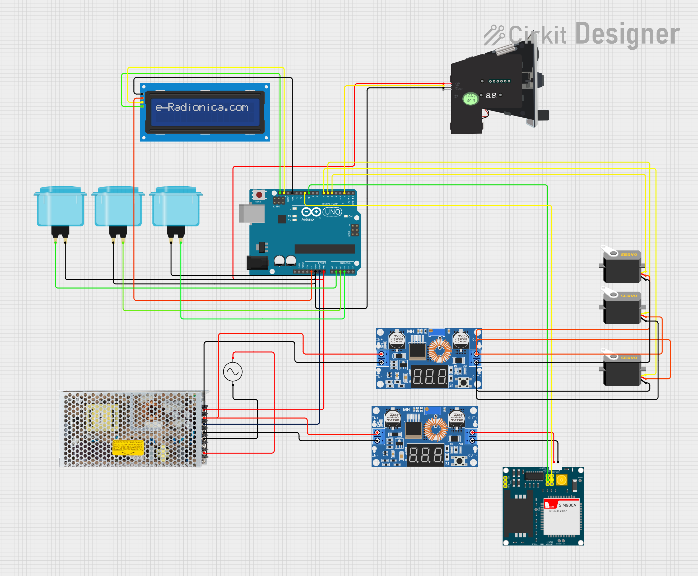
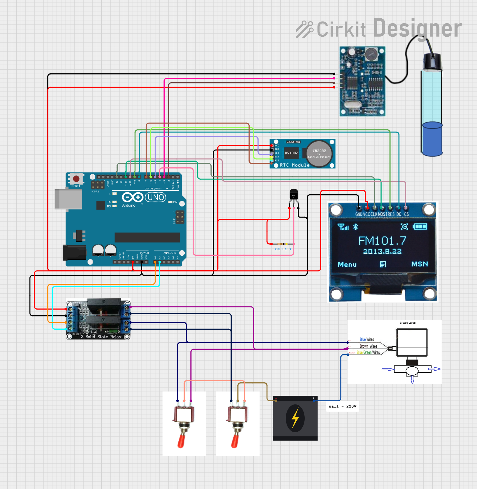
Explore Projects Built with Контроллер
Common Applications and Use Cases
- Industrial Automation: Managing machinery and production lines.
- Robotics: Controlling robotic arms, motors, and sensors.
- Home Automation: Regulating smart home devices like thermostats and lighting.
- Embedded Systems: Acting as the central control unit in microcontroller-based projects.
- Process Control: Maintaining desired parameters such as temperature, pressure, or speed.
Technical Specifications
The technical specifications of a Контроллер can vary depending on its type and application. Below are general specifications for a typical microcontroller-based controller:
General Specifications
- Operating Voltage: 3.3V to 5V
- Input Voltage Range: 7V to 12V (for onboard voltage regulators)
- Current Consumption: 50mA to 500mA (depending on peripherals)
- Processor: 8-bit, 16-bit, or 32-bit microcontroller
- Clock Speed: 8 MHz to 72 MHz
- Memory:
- Flash: 16KB to 512KB
- SRAM: 2KB to 64KB
- Communication Interfaces: UART, SPI, I2C, CAN, USB
- GPIO Pins: 10 to 40 (depending on the model)
- PWM Channels: 4 to 16
- Analog Inputs: 6 to 16 channels (10-bit or 12-bit ADC)
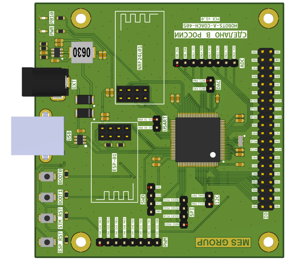
Pin Configuration and Descriptions
Below is an example of a typical 28-pin Контроллер pinout:
| Pin Number | Pin Name | Description |
|---|---|---|
| 1 | VCC | Power supply input (3.3V or 5V) |
| 2 | GND | Ground |
| 3 | RESET | Reset input (active low) |
| 4 | RX | UART Receive |
| 5 | TX | UART Transmit |
| 6 | SDA | I2C Data Line |
| 7 | SCL | I2C Clock Line |
| 8 | PWM1 | PWM Output Channel 1 |
| 9 | PWM2 | PWM Output Channel 2 |
| 10 | ADC0 | Analog Input Channel 0 |
| 11 | ADC1 | Analog Input Channel 1 |
| 12 | GPIO1 | General Purpose Input/Output Pin 1 |
| 13 | GPIO2 | General Purpose Input/Output Pin 2 |
| 14 | GPIO3 | General Purpose Input/Output Pin 3 |
| 15 | GPIO4 | General Purpose Input/Output Pin 4 |
| 16 | GPIO5 | General Purpose Input/Output Pin 5 |
| 17 | GPIO6 | General Purpose Input/Output Pin 6 |
| 18 | GPIO7 | General Purpose Input/Output Pin 7 |
| 19 | GPIO8 | General Purpose Input/Output Pin 8 |
| 20 | INT0 | External Interrupt 0 |
| 21 | INT1 | External Interrupt 1 |
| 22 | SPI_MOSI | SPI Master Out Slave In |
| 23 | SPI_MISO | SPI Master In Slave Out |
| 24 | SPI_SCK | SPI Clock |
| 25 | SPI_SS | SPI Slave Select |
| 26 | AREF | Analog Reference Voltage |
| 27 | XTAL1 | External Oscillator Input |
| 28 | XTAL2 | External Oscillator Output |
Usage Instructions
How to Use the Контроллер in a Circuit
- Power Supply: Connect the VCC pin to a regulated 3.3V or 5V power source and the GND pin to ground.
- Programming: Use a compatible programmer or USB-to-serial adapter to upload firmware to the controller.
- Peripheral Connections:
- Connect sensors to the analog or digital input pins.
- Connect actuators (e.g., motors, LEDs) to the GPIO or PWM output pins.
- Communication: Use UART, SPI, or I2C interfaces to communicate with other devices or microcontrollers.
- External Oscillator: If required, connect an external crystal oscillator to the XTAL1 and XTAL2 pins.
Important Considerations and Best Practices
- Voltage Levels: Ensure all connected devices operate at the same voltage level as the controller to avoid damage.
- Decoupling Capacitors: Place decoupling capacitors (e.g., 0.1µF) near the power pins to reduce noise.
- Pull-Up/Pull-Down Resistors: Use pull-up or pull-down resistors on input pins to prevent floating states.
- Heat Management: If the controller operates at high current, ensure proper heat dissipation.
- Firmware Updates: Regularly update the firmware to fix bugs and improve performance.
Example: Using Контроллер with Arduino UNO
Below is an example of how to use a Контроллер to control an LED using an Arduino UNO:
// Example: Blink an LED connected to GPIO1 of the Контроллер

#define LED_PIN 2  // GPIO1 of the Контроллер is connected to Arduino pin 2

void setup() {
  pinMode(LED_PIN, OUTPUT);  // Set the LED pin as an output
}

void loop() {
  digitalWrite(LED_PIN, HIGH);  // Turn the LED on
  delay(1000);                  // Wait for 1 second
  digitalWrite(LED_PIN, LOW);   // Turn the LED off
  delay(1000);                  // Wait for 1 second
}
Troubleshooting and FAQs
Common Issues and Solutions
Controller Not Powering On:
- Check the power supply voltage and ensure it matches the controller's requirements.
- Verify all connections to the VCC and GND pins.
Unable to Upload Firmware:
- Ensure the correct COM port is selected in the programming software.
- Check the connection between the programmer and the controller.
- Press the RESET button before uploading the firmware.
Peripheral Devices Not Responding:
- Verify the wiring and connections to the peripheral devices.
- Check the voltage levels and ensure compatibility with the controller.
Controller Overheating:
- Reduce the current load on the GPIO pins.
- Add a heatsink or improve ventilation around the controller.
FAQs
Q: Can I use the Контроллер with a 12V power supply?
A: Yes, if the controller has an onboard voltage regulator. Otherwise, use a step-down converter.Q: How many devices can I connect via I2C?
A: The I2C bus supports up to 127 devices, but the actual number depends on the bus capacitance and pull-up resistors.Q: What is the maximum current output of the GPIO pins?
A: Typically, GPIO pins can source or sink up to 20mA. Check the datasheet for exact values.Q: Can I use the Контроллер for real-time applications?
A: Yes, but ensure the controller's processing speed and memory are sufficient for your application.