How to Use MULTI TIMER: Examples, Pinouts, and Specs
Introduction
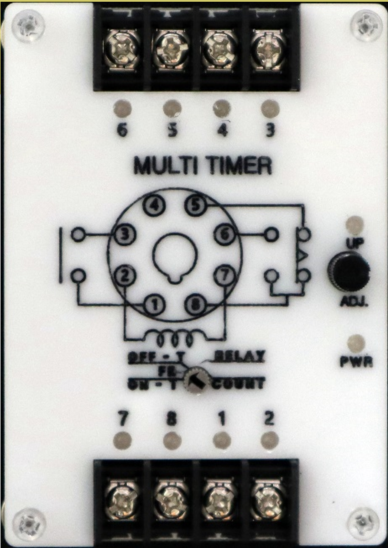
The MULTI TIMER, manufactured by Cirkit (Part ID: MULTI TIMER), is a versatile electronic device designed to perform multiple timing functions. It can be programmed to control the on/off states of connected devices at predefined intervals. This component is widely used in automation systems, lighting control, event scheduling, and other time-based applications. Its flexibility and ease of use make it an essential tool for both hobbyists and professionals.
Explore Projects Built with MULTI TIMER

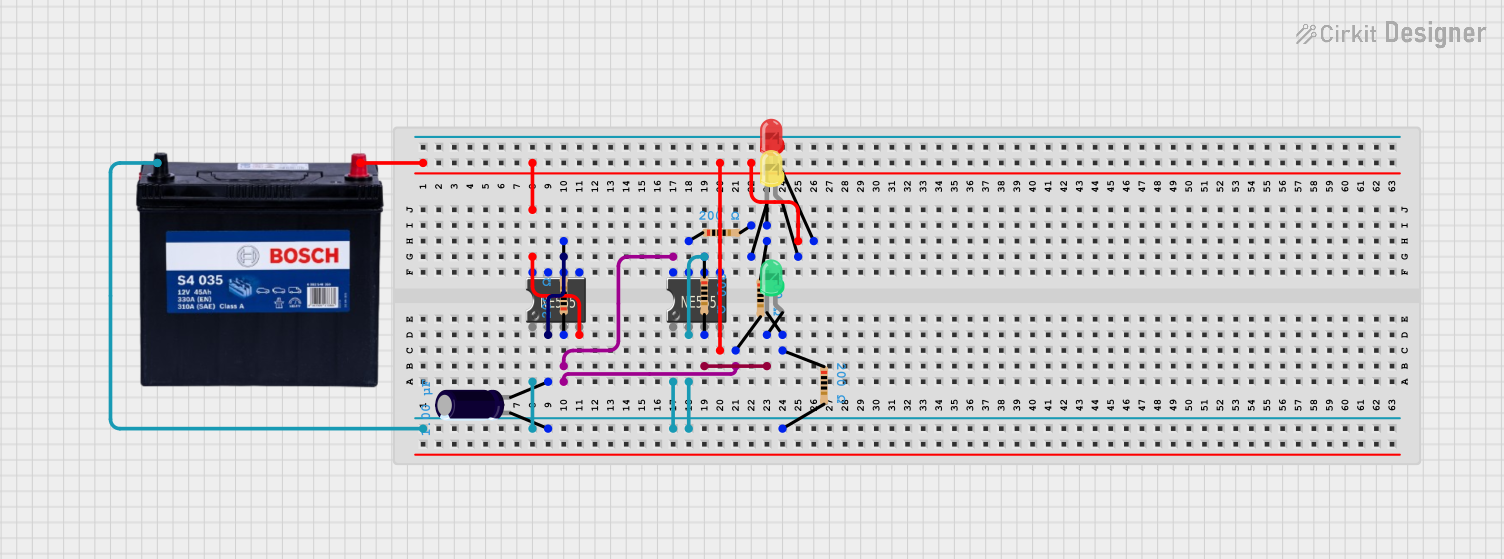
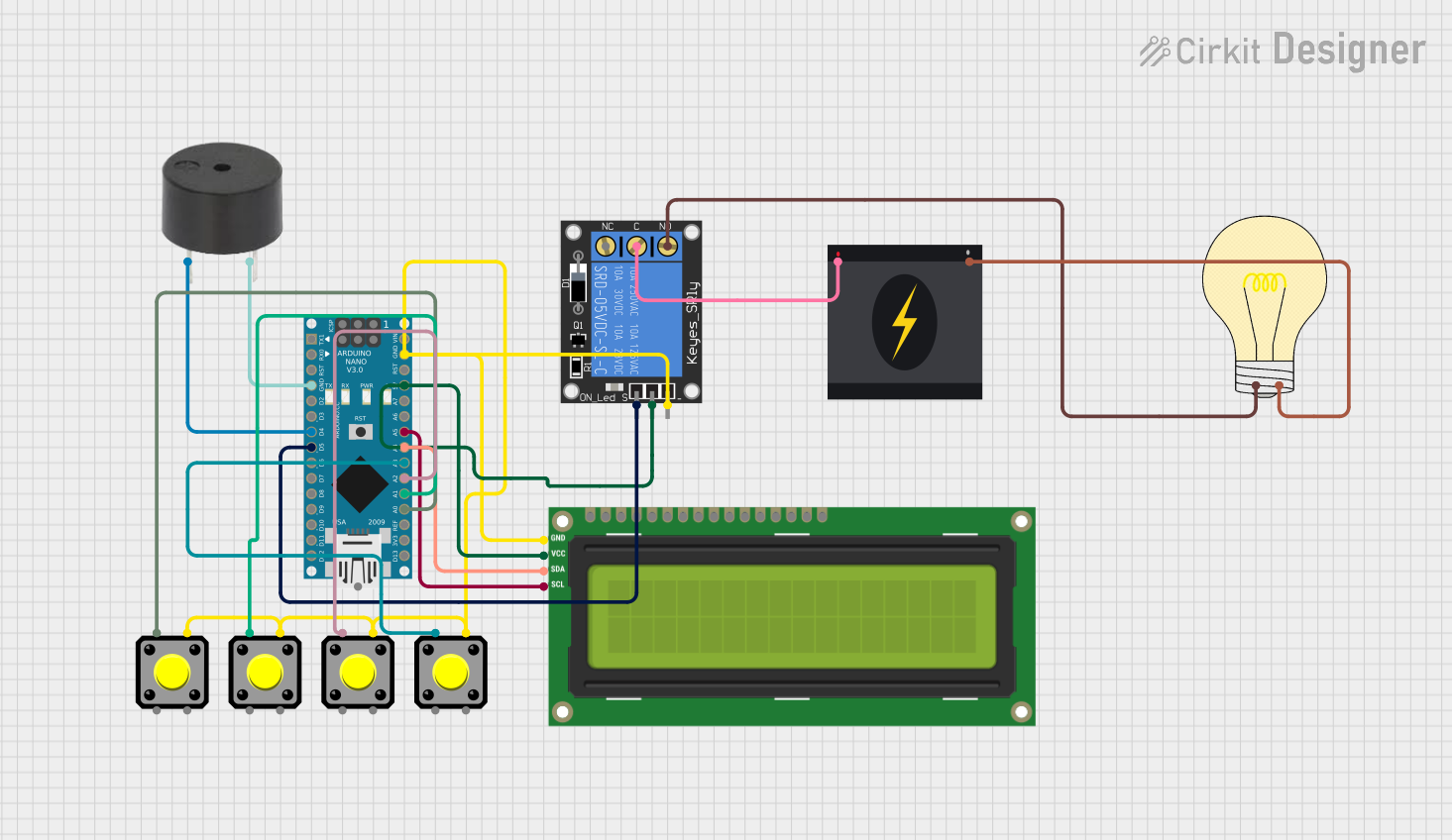
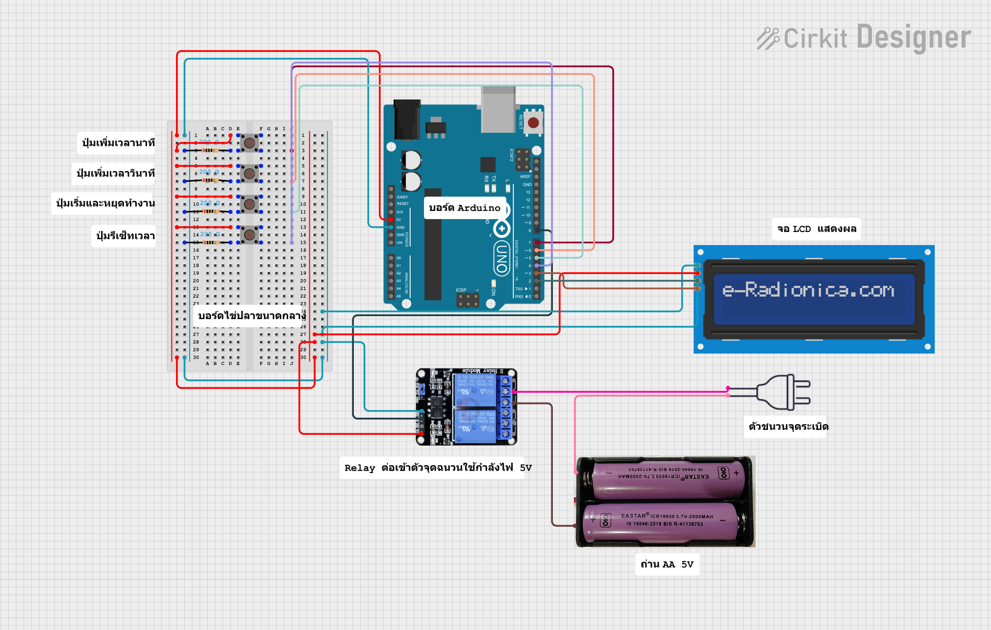
Explore Projects Built with MULTI TIMER
Technical Specifications
The MULTI TIMER is designed to operate efficiently in a variety of environments. Below are its key technical details:
General Specifications
- Manufacturer: Cirkit
- Part ID: MULTI TIMER
- Operating Voltage: 5V to 24V DC
- Current Consumption: ≤ 50mA
- Timing Range: 0.1 seconds to 999 minutes (programmable)
- Output Type: Relay (NO/NC)
- Relay Output Rating: 10A at 250V AC or 10A at 30V DC
- Trigger Input: High-level trigger (3V to 24V DC)
- Operating Temperature: -20°C to 60°C
- Dimensions: 60mm x 30mm x 20mm
Pin Configuration and Descriptions
The MULTI TIMER has a simple pinout for easy integration into circuits. Below is the pin configuration:
| Pin Name | Description |
|---|---|
| VCC | Positive power supply input (5V to 24V) |
| GND | Ground connection |
| TRIG | Trigger input for starting the timer |
| NO | Normally Open relay output |
| NC | Normally Closed relay output |
| COM | Common terminal for relay output |
Usage Instructions
The MULTI TIMER is straightforward to use and can be integrated into a variety of circuits. Follow the steps below to use the component effectively:
Basic Setup
- Power Connection: Connect the VCC pin to a DC power supply (5V to 24V) and the GND pin to the ground.
- Trigger Input: Connect the TRIG pin to a high-level signal (3V to 24V DC) to start the timer.
- Relay Output: Use the NO, NC, and COM pins to control the connected load (e.g., a light or motor). For example:
- Connect the load between the NO pin and the power supply.
- Connect the COM pin to the ground or the other terminal of the power supply.
Programming the Timer
The MULTI TIMER can be programmed using onboard buttons or an external microcontroller. The timing range (0.1 seconds to 999 minutes) can be set by adjusting the parameters via the onboard interface.
Example: Using MULTI TIMER with Arduino UNO
The MULTI TIMER can be triggered using an Arduino UNO. Below is an example code to send a high-level signal to the TRIG pin:
// Example code to trigger the MULTI TIMER using Arduino UNO
const int triggerPin = 7; // Pin connected to the TRIG pin of MULTI TIMER

void setup() {
  pinMode(triggerPin, OUTPUT); // Set triggerPin as an output
  digitalWrite(triggerPin, LOW); // Ensure the pin starts LOW
}

void loop() {
  digitalWrite(triggerPin, HIGH); // Send a high-level signal to start the timer
  delay(1000); // Keep the signal HIGH for 1 second
  digitalWrite(triggerPin, LOW); // Set the pin LOW to stop the signal
  delay(5000); // Wait for 5 seconds before triggering again
}
Important Considerations
- Ensure the power supply voltage matches the operating voltage range of the MULTI TIMER.
- Avoid exceeding the relay output rating (10A at 250V AC or 10A at 30V DC).
- Use proper insulation and safety measures when working with high voltages.
- If using the timer in a noisy environment, consider adding a capacitor across the power supply pins to reduce noise.
Troubleshooting and FAQs
Common Issues and Solutions
The timer does not start when triggered.
- Ensure the TRIG pin receives a high-level signal (3V to 24V DC).
- Check the power supply connections and ensure the voltage is within the specified range.
The relay does not activate.
- Verify the load connections to the NO, NC, and COM pins.
- Ensure the load does not exceed the relay's maximum rating.
The timer behaves erratically.
- Check for noise in the power supply and add a decoupling capacitor if necessary.
- Ensure the operating temperature is within the specified range (-20°C to 60°C).
The timer does not retain settings after power loss.
- The MULTI TIMER does not have non-volatile memory. Reprogram the settings after power is restored.
FAQs
Q: Can the MULTI TIMER be used with AC loads?
A: Yes, the relay output supports AC loads up to 10A at 250V AC. Ensure proper insulation and safety precautions.
Q: How precise is the timing function?
A: The timing accuracy is ±0.1%, making it suitable for most applications requiring precise timing.
Q: Can I use the MULTI TIMER with a 3.3V microcontroller?
A: Yes, the TRIG pin can accept signals as low as 3V, making it compatible with 3.3V logic levels.
Q: Is the MULTI TIMER suitable for outdoor use?
A: The component is not weatherproof. Use an appropriate enclosure to protect it from moisture and dust in outdoor applications.
By following this documentation, users can effectively integrate the MULTI TIMER into their projects and troubleshoot common issues with ease.