How to Use FAN 12V: Examples, Pinouts, and Specs
Introduction
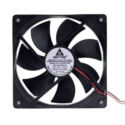
The FAN 12V is a compact and efficient cooling fan designed to operate at a nominal voltage of 12 volts. It is widely used in electronic systems to dissipate heat, ensuring the longevity and optimal performance of components. This fan is commonly found in applications such as computer cooling, power supply ventilation, and general-purpose airflow management in electronic enclosures.
Explore Projects Built with FAN 12V


Explore Projects Built with FAN 12V
Common Applications and Use Cases
- Cooling for microcontrollers, processors, and power transistors
- Ventilation in power supplies and battery packs
- Air circulation in 3D printers, robotics, and other DIY projects
- Heat dissipation in industrial and consumer electronics
Technical Specifications
The following table outlines the key technical details of the FAN 12V:
| Parameter | Value |
|---|---|
| Operating Voltage | 12V DC |
| Operating Current | 0.1A to 0.3A (typical) |
| Power Consumption | 1.2W to 3.6W |
| Airflow | 20-50 CFM (varies by model) |
| Fan Speed | 2000-5000 RPM (varies by model) |
| Noise Level | 20-35 dBA (varies by model) |
| Dimensions | Common sizes: 40mm, 60mm, 80mm, 120mm |
| Connector Type | 2-pin or 3-pin JST/Molex |
| Bearing Type | Sleeve or Ball Bearing |
| Lifespan | 30,000 to 50,000 hours |
Pin Configuration and Descriptions
The FAN 12V typically comes with either a 2-pin or 3-pin connector. The pinout is as follows:
2-Pin Connector
| Pin Number | Wire Color | Description |
|---|---|---|
| 1 | Red | Positive (+12V) |
| 2 | Black | Ground (GND) |
3-Pin Connector
| Pin Number | Wire Color | Description |
|---|---|---|
| 1 | Red | Positive (+12V) |
| 2 | Black | Ground (GND) |
| 3 | Yellow | Tachometer (Speed Feedback) |
Usage Instructions
How to Use the FAN 12V in a Circuit
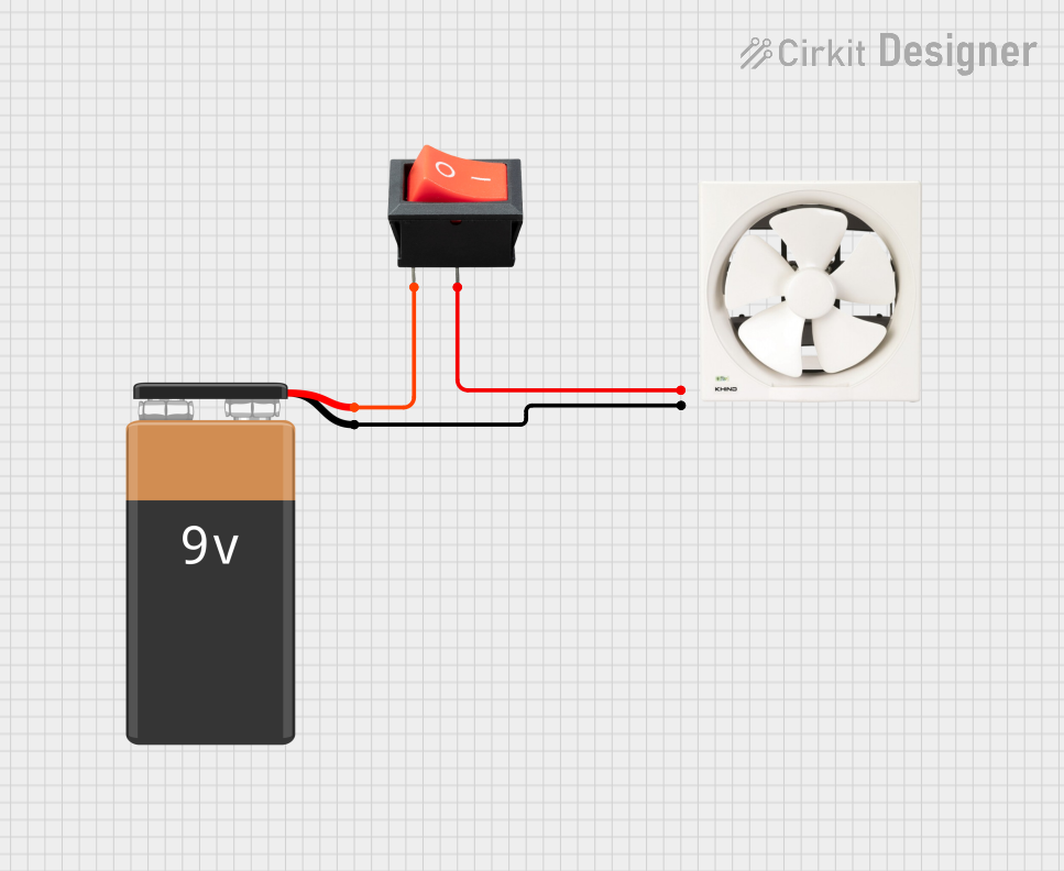
- Power Supply: Connect the red wire to a 12V DC power source and the black wire to ground. Ensure the power supply can provide sufficient current for the fan's operation.
- Mounting: Secure the fan in place using screws or adhesive mounts. Ensure proper airflow direction by checking the fan's markings (airflow direction is usually indicated by arrows on the fan housing).
- Optional Speed Monitoring: If using a 3-pin fan, connect the yellow wire to a microcontroller or monitoring circuit to read the fan's speed (tachometer output).
Important Considerations and Best Practices
- Voltage Tolerance: Do not exceed the rated 12V operating voltage to avoid damaging the fan.
- Current Supply: Ensure the power source can supply the required current, especially for high-speed fans.
- Airflow Direction: Install the fan with the correct orientation to ensure proper cooling.
- Noise Reduction: Use rubber mounts or grommets to minimize vibration and noise.
- Dust Management: Periodically clean the fan blades and housing to prevent dust buildup, which can reduce efficiency and increase noise.
Example: Connecting FAN 12V to an Arduino UNO
The FAN 12V can be controlled using an Arduino UNO and a transistor for switching. Below is an example circuit and code:
Circuit Diagram
- Connect the red wire of the fan to the collector of an NPN transistor (e.g., 2N2222).
- Connect the black wire of the fan to ground.
- Connect the emitter of the transistor to ground.
- Connect a 1kΩ resistor between the base of the transistor and a PWM-capable pin on the Arduino (e.g., Pin 9).
- Connect a 12V power supply to the fan's red wire and the Arduino's ground.
Arduino Code
// Example code to control a 12V fan using PWM on an Arduino UNO
// Ensure the fan is connected via a transistor for proper switching

const int fanPin = 9; // PWM pin connected to the transistor base

void setup() {
  pinMode(fanPin, OUTPUT); // Set the fan control pin as output
}

void loop() {
  analogWrite(fanPin, 128); // Set fan speed to 50% (PWM value: 128 out of 255)
  delay(5000); // Run at 50% speed for 5 seconds

  analogWrite(fanPin, 255); // Set fan speed to 100% (PWM value: 255)
  delay(5000); // Run at full speed for 5 seconds
}
Troubleshooting and FAQs
Common Issues and Solutions
Fan Not Spinning
- Cause: Insufficient power supply or incorrect wiring.
- Solution: Verify the power supply voltage and current. Check the wiring connections.
Excessive Noise
- Cause: Dust buildup, misalignment, or worn bearings.
- Solution: Clean the fan blades and housing. Ensure the fan is mounted securely. Replace the fan if bearings are worn.
Fan Spins Slowly
- Cause: Insufficient voltage or high resistance in the circuit.
- Solution: Check the power supply voltage and ensure proper connections.
Tachometer Signal Not Detected
- Cause: Incorrect connection or incompatible monitoring circuit.
- Solution: Verify the yellow wire connection and ensure the monitoring circuit is compatible with the tachometer output.
FAQs
Q: Can I use the FAN 12V with a 5V power supply?
A: No, the FAN 12V is designed to operate at 12V. Using a lower voltage will result in reduced performance or failure to spin.
Q: How do I reduce fan noise?
A: Use rubber mounts to minimize vibration, clean the fan regularly, and consider using a fan with a lower RPM rating.
Q: Can I control the fan speed without a microcontroller?
A: Yes, you can use a variable resistor (potentiometer) or a dedicated fan speed controller circuit to adjust the voltage supplied to the fan.
Q: What is the purpose of the yellow wire on a 3-pin fan?
A: The yellow wire provides a tachometer signal, which can be used to monitor the fan's speed in real-time.