How to Use Mini PDB: Examples, Pinouts, and Specs
Introduction
A Mini Power Distribution Board (PDB) is a compact circuit board designed to simplify power management in electronic projects. It is commonly used in drones, RC vehicles, and other multi-component systems to distribute power from a single battery to multiple components, such as motors, electronic speed controllers (ESCs), and flight controllers. By centralizing power distribution, the Mini PDB reduces wiring complexity, improves efficiency, and ensures a cleaner and more organized setup.
Explore Projects Built with Mini PDB


Explore Projects Built with Mini PDB
Common Applications and Use Cases
- Drones and Quadcopters: Distributing power to motors, ESCs, and flight controllers.
- RC Vehicles: Powering servos, motors, and other electronic components.
- Robotics: Managing power for multiple actuators and sensors.
- DIY Electronics Projects: Simplifying power distribution in multi-component systems.
Technical Specifications
Below are the key technical details of a typical Mini PDB:
| Parameter | Specification |
|---|---|
| Input Voltage Range | 7V to 26V (2S to 6S LiPo batteries) |
| Maximum Current Rating | 100A (total) |
| Output Voltage Options | 5V and 12V regulated outputs |
| Dimensions | 36mm x 36mm |
| Weight | ~10g |
| Mounting Hole Spacing | 30.5mm x 30.5mm (standard for drones) |
| PCB Material | FR4 (flame-retardant material) |
| Connector Type | Solder pads or XT60 input connector |
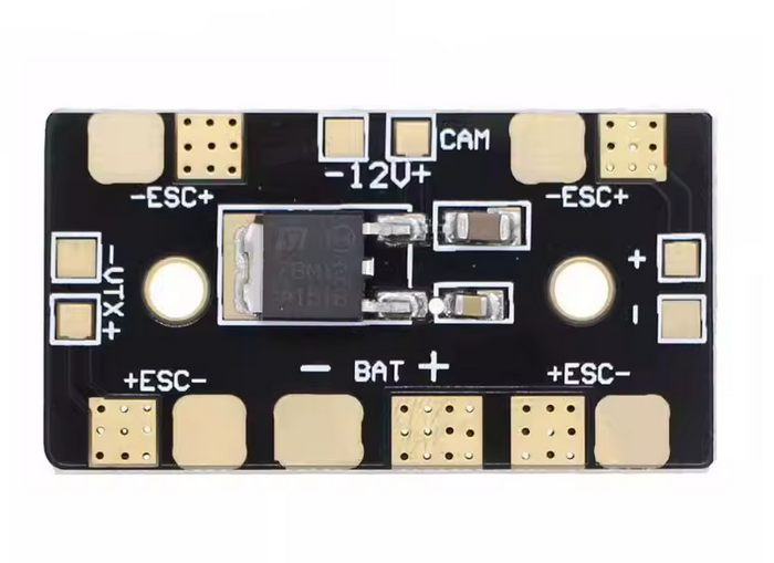
Pin Configuration and Descriptions
The Mini PDB typically features solder pads for input and output connections. Below is a table describing the key pads and their functions:
| Pad/Connector | Description |
|---|---|
| Battery Input | Connects to the main battery (e.g., 2S-6S LiPo). Typically marked as + and -. |
| ESC Outputs | Distributes power to the ESCs. Usually four sets of + and - pads for quadcopters. |
| 5V Output | Provides regulated 5V output for powering flight controllers or other components. |
| 12V Output | Provides regulated 12V output for cameras, video transmitters, or LEDs. |
| Ground (GND) | Common ground connection for all components. |
Usage Instructions
How to Use the Mini PDB in a Circuit
- Connect the Battery: Solder the battery leads to the
+and-input pads on the Mini PDB. Ensure proper polarity to avoid damage. - Connect ESCs: Solder the power leads of each ESC to the corresponding
+and-output pads. For quadcopters, connect one ESC to each set of pads. - Regulated Outputs: Use the 5V and 12V output pads to power components like flight controllers, cameras, or LEDs. Ensure the connected devices are compatible with the output voltage.
- Mounting: Secure the Mini PDB to your frame using the mounting holes. Ensure it is insulated from conductive surfaces to prevent short circuits.
Important Considerations and Best Practices
- Check Polarity: Always double-check the polarity of connections to avoid damaging the PDB or connected components.
- Current Limits: Ensure the total current draw does not exceed the PDB's maximum current rating (100A).
- Heat Management: If the PDB gets hot during operation, consider adding ventilation or a heat sink to improve cooling.
- Insulation: Use heat shrink tubing or electrical tape to insulate exposed solder joints and prevent short circuits.
- Testing: Before powering the system, use a multimeter to verify all connections and check for shorts.
Example: Connecting a Mini PDB to an Arduino UNO
If you are using the Mini PDB to power an Arduino UNO, you can connect the 5V regulated output to the Arduino's 5V pin and the ground to the GND pin. Below is an example Arduino sketch to control an LED powered via the Mini PDB:
// Example Arduino code to control an LED powered by the Mini PDB

const int ledPin = 13; // Pin connected to the LED

void setup() {
  pinMode(ledPin, OUTPUT); // Set the LED pin as an output
}

void loop() {
  digitalWrite(ledPin, HIGH); // Turn the LED on
  delay(1000);                // Wait for 1 second
  digitalWrite(ledPin, LOW);  // Turn the LED off
  delay(1000);                // Wait for 1 second
}
Troubleshooting and FAQs
Common Issues and Solutions
PDB Not Powering Components
- Cause: Incorrect battery connection or polarity.
- Solution: Verify the battery is connected to the correct input pads (
+and-) and check for proper polarity.
Overheating
- Cause: Excessive current draw or poor ventilation.
- Solution: Ensure the total current draw is within the PDB's rating. Improve airflow or add a heat sink if necessary.
Short Circuit
- Cause: Exposed solder joints or incorrect wiring.
- Solution: Inspect all connections for shorts using a multimeter. Insulate exposed joints with heat shrink tubing or electrical tape.
Regulated Outputs Not Working
- Cause: Overloading the 5V or 12V output.
- Solution: Check the current draw of connected devices and ensure it does not exceed the PDB's output capacity.
FAQs
Can I use the Mini PDB with a 1S LiPo battery?
- No, the Mini PDB requires a minimum input voltage of 7V (2S LiPo).
What is the maximum power output of the Mini PDB?
- The maximum power output depends on the input voltage and current rating. For example, at 12V and 100A, the maximum power is 1200W.
Can I use the Mini PDB for non-drone applications?
- Yes, the Mini PDB can be used in any project requiring efficient power distribution, such as robotics or DIY electronics.
How do I mount the Mini PDB?
- Use the mounting holes (30.5mm x 30.5mm spacing) to secure the PDB to your frame with screws or standoffs.
By following this documentation, you can effectively integrate the Mini PDB into your projects and ensure reliable power distribution.