
How to Use TC4427CPA: Examples, Pinouts, and Specs
 Design with TC4427CPA in Cirkit Designer
Introduction
The TC4427CPA is a dual high-speed CMOS buffer/driver manufactured by Microchip Technology. It is designed to drive capacitive loads with high efficiency and low output impedance. This component is capable of operating with supply voltages up to 15V, making it ideal for applications requiring signal buffering, level shifting, or driving MOSFET gates.
Explore Projects Built with TC4427CPA
 Open Project in Cirkit Designer
 Open Project in Cirkit Designer
 Open Project in Cirkit Designer
 Open Project in Cirkit Designer
Explore Projects Built with TC4427CPA
Open Project in Cirkit DesignerOpen Project in Cirkit DesignerOpen Project in Cirkit DesignerOpen Project in Cirkit DesignerCommon Applications
- Driving capacitive loads
- MOSFET gate driving
- Signal buffering and level shifting
- Pulse transformer driving
- Motor control circuits
Technical Specifications
Key Technical Details
| Parameter | Value |
|---|---|
| Manufacturer | Microchip Technology |
| Part Number | TC4427CPA |
| Supply Voltage (VDD) | 4.5V to 18V |
| Output Voltage Range | 0V to VDD |
| Output Current (Peak) | ±1.5A |
| Input Voltage Range | 0V to VDD |
| Propagation Delay | 25ns (typical) |
| Operating Temperature | -40°C to +85°C |
| Package Type | 8-pin PDIP |
Pin Configuration and Descriptions
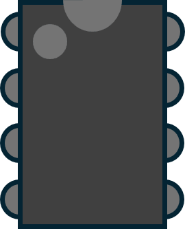
The TC4427CPA is an 8-pin device with the following pinout:
| Pin Number | Pin Name | Description |
|---|---|---|
| 1 | IN A | Input signal for Channel A |
| 2 | GND | Ground (0V reference) |
| 3 | IN B | Input signal for Channel B |
| 4 | OUT B | Output signal for Channel B |
| 5 | VDD | Positive supply voltage |
| 6 | OUT A | Output signal for Channel A |
| 7 | NC | No connection (leave unconnected) |
| 8 | NC | No connection (leave unconnected) |
Usage Instructions
How to Use the TC4427CPA in a Circuit
- Power Supply: Connect the VDD pin to a stable power supply within the range of 4.5V to 18V. Connect the GND pin to the circuit ground.
- Input Signals: Apply logic-level signals (0V to VDD) to the IN A and IN B pins. These inputs control the corresponding outputs (OUT A and OUT B).
- Output Connections: Connect the OUT A and OUT B pins to the load you wish to drive. Ensure the load does not exceed the maximum output current of ±1.5A.
- Bypass Capacitor: Place a 0.1µF ceramic capacitor close to the VDD and GND pins to stabilize the power supply and reduce noise.
Important Considerations and Best Practices
- Input Voltage Levels: Ensure the input signals are within the range of 0V to VDD to avoid damage to the device.
- Thermal Management: If driving high-current loads, ensure proper heat dissipation to prevent overheating.
- Unused Pins: Leave the NC pins unconnected. Do not use them as additional ground or power connections.
- Decoupling Capacitor: Always use a decoupling capacitor (0.1µF) near the VDD pin to minimize power supply noise.
Example: Using TC4427CPA with Arduino UNO
The TC4427CPA can be used to drive a MOSFET gate from an Arduino UNO. Below is an example circuit and code:
Circuit Description
- Connect the Arduino digital pin (e.g., D3) to the IN A pin of the TC4427CPA.
- Connect the OUT A pin to the gate of the MOSFET.
- Connect the VDD pin to a 12V power supply and the GND pin to the common ground.
Arduino Code
// Example code to drive a MOSFET using TC4427CPA and Arduino UNO

const int driverPin = 3; // Pin connected to IN A of TC4427CPA

void setup() {
  pinMode(driverPin, OUTPUT); // Set the driver pin as an output
}

void loop() {
  digitalWrite(driverPin, HIGH); // Turn on the MOSFET
  delay(1000); // Wait for 1 second
  digitalWrite(driverPin, LOW);  // Turn off the MOSFET
  delay(1000); // Wait for 1 second
}
Troubleshooting and FAQs
Common Issues and Solutions
No Output Signal:
- Cause: Incorrect power supply or input signal.
- Solution: Verify that the VDD pin is connected to a stable power supply and the input signal is within the 0V to VDD range.
Overheating:
- Cause: Excessive load current or insufficient heat dissipation.
- Solution: Ensure the load current does not exceed ±1.5A. Use a heatsink or improve ventilation if necessary.
Noise or Instability:
- Cause: Missing or insufficient decoupling capacitor.
- Solution: Add a 0.1µF ceramic capacitor close to the VDD and GND pins.
Output Voltage Too Low:
- Cause: High load capacitance or incorrect wiring.
- Solution: Check the load capacitance and ensure proper wiring. Reduce the load capacitance if possible.
FAQs
Q1: Can the TC4427CPA drive inductive loads?
A1: Yes, but you must use a flyback diode across the load to protect the driver from voltage spikes caused by inductive kickback.
Q2: What is the maximum switching frequency of the TC4427CPA?
A2: The TC4427CPA can operate at frequencies up to several hundred kHz, depending on the load capacitance and supply voltage.
Q3: Can I use the TC4427CPA with a 3.3V logic input?
A3: Yes, as long as the VDD supply voltage is 4.5V or higher, the TC4427CPA can accept 3.3V logic inputs.
Q4: What happens if I leave the input pins floating?
A4: Floating input pins may cause unpredictable behavior. Always connect unused inputs to GND or VDD through a pull-down or pull-up resistor, respectively.