How to Use mks apt v1.0: Examples, Pinouts, and Specs
Introduction
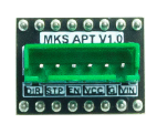
The MKS APT V1.0 is a precision 3D printer controller board designed for high-performance applications. It features advanced motion control algorithms, support for multiple stepper drivers, and a user-friendly interface for easy configuration and operation. This board is ideal for 3D printing enthusiasts and professionals seeking reliable and efficient control over their 3D printers.
Explore Projects Built with mks apt v1.0
Explore Projects Built with mks apt v1.0
Common Applications and Use Cases
- 3D printers for hobbyists and professionals
- CNC machines requiring precise motion control
- Robotics projects with multiple stepper motors
- Educational and research projects involving motion control systems
Technical Specifications
Key Technical Details
- Microcontroller: 32-bit ARM Cortex-M3 processor
- Input Voltage: 12V–24V DC
- Stepper Driver Support: Up to 5 independent stepper motor drivers (e.g., TMC2209, A4988)
- Communication Interfaces: USB, UART, and I2C
- Display Support: Compatible with LCD and touchscreen displays
- Heater Outputs: 2 (for hotend and heated bed)
- Fan Outputs: 2 controllable fan outputs
- Endstop Inputs: 3 (X, Y, Z axes)
- Expansion Ports: Multiple GPIO pins for additional peripherals
- Dimensions: 110mm x 85mm
Pin Configuration and Descriptions
The MKS APT V1.0 features a well-labeled pinout for easy connection. Below is a table describing the key pins:
| Pin Name | Description |
|---|---|
X_STEP, X_DIR |
Step and direction signals for the X-axis stepper motor |
Y_STEP, Y_DIR |
Step and direction signals for the Y-axis stepper motor |
Z_STEP, Z_DIR |
Step and direction signals for the Z-axis stepper motor |
E_STEP, E_DIR |
Step and direction signals for the extruder stepper motor |
HEAT0, HEAT1 |
Outputs for hotend and heated bed control |
FAN0, FAN1 |
Outputs for controllable fans |
ENDSTOP_X, ENDSTOP_Y, ENDSTOP_Z |
Inputs for X, Y, and Z endstop switches |
LCD |
Interface for connecting an LCD or touchscreen display |
EXP1, EXP2 |
Expansion ports for additional peripherals |
POWER_IN |
Main power input (12V–24V DC) |
USB |
USB interface for firmware updates and communication |
Usage Instructions
How to Use the MKS APT V1.0 in a Circuit
- Power Supply: Connect a 12V–24V DC power supply to the
POWER_INterminals. Ensure the power supply can handle the current requirements of your motors and heaters. - Stepper Drivers: Insert compatible stepper drivers (e.g., TMC2209, A4988) into the designated sockets. Adjust the driver current settings as needed.
- Motors: Connect stepper motors to the
X,Y,Z, andEmotor outputs. Ensure proper wiring to avoid damage. - Endstops: Attach endstop switches to the
ENDSTOP_X,ENDSTOP_Y, andENDSTOP_Zinputs. - Heaters and Fans: Connect the hotend and heated bed to
HEAT0andHEAT1, respectively. Attach fans toFAN0andFAN1. - Display: Connect an LCD or touchscreen display to the
LCDorEXPports. - Firmware: Install compatible firmware (e.g., Marlin) via the USB interface. Configure the firmware to match your hardware setup.
Important Considerations and Best Practices
- Cooling: Ensure proper cooling for the stepper drivers to prevent overheating. Use heatsinks and fans if necessary.
- Firmware Configuration: Double-check firmware settings for motor steps, endstop polarity, and thermistor types.
- Wiring: Verify all connections before powering on the board to avoid short circuits or damage.
- Stepper Driver Orientation: Insert stepper drivers in the correct orientation as indicated on the board.
Example Code for Arduino UNO (Communication with MKS APT V1.0)
The MKS APT V1.0 can communicate with an Arduino UNO via UART. Below is an example code snippet for sending commands:
#include <SoftwareSerial.h>

// Define RX and TX pins for communication with MKS APT V1.0
SoftwareSerial mksSerial(10, 11); // RX = pin 10, TX = pin 11

void setup() {
  // Initialize serial communication
  Serial.begin(9600); // For debugging via Serial Monitor
  mksSerial.begin(115200); // Communication with MKS APT V1.0

  Serial.println("MKS APT V1.0 Communication Initialized");
}

void loop() {
  // Example: Send a G-code command to the MKS APT V1.0
  mksSerial.println("G28"); // Home all axes
  delay(1000); // Wait for the command to execute

  // Check for responses from the MKS APT V1.0
  if (mksSerial.available()) {
    String response = mksSerial.readString();
    Serial.println("Response from MKS APT V1.0: " + response);
  }
}
Troubleshooting and FAQs
Common Issues and Solutions
Stepper Motors Not Moving
- Cause: Incorrect wiring or stepper driver configuration.
- Solution: Verify motor connections and ensure the stepper drivers are properly seated and configured.
Heaters Not Heating
- Cause: Faulty wiring or incorrect firmware settings.
- Solution: Check heater connections and ensure the correct thermistor type is configured in the firmware.
No Communication via USB
- Cause: Missing drivers or incorrect baud rate.
- Solution: Install the necessary USB drivers and ensure the baud rate matches the firmware settings.
LCD/Touchscreen Not Displaying
- Cause: Incorrect wiring or incompatible display.
- Solution: Verify the display connections and ensure compatibility with the MKS APT V1.0.
FAQs
Q: Can I use the MKS APT V1.0 with other firmware besides Marlin?
- A: Yes, the board is compatible with other firmware like Repetier and Smoothieware, but Marlin is the most commonly used.
Q: What stepper drivers are recommended for silent operation?
- A: TMC2209 or TMC2130 drivers are recommended for quiet and smooth operation.
Q: How do I update the firmware?
- A: Connect the board to your computer via USB, use a tool like Arduino IDE or a dedicated firmware flasher, and upload the firmware.
Q: Can I add more stepper motors?
- A: Yes, you can use the expansion ports to add additional stepper drivers if needed.
This documentation provides a comprehensive guide to using the MKS APT V1.0 effectively. For further assistance, refer to the official MKS documentation or community forums.