How to Use Relay Omron MY2N: Examples, Pinouts, and Specs
Introduction
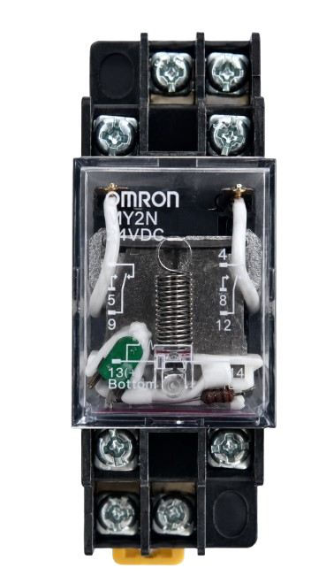
The Omron MY2N is a general-purpose electromagnetic relay designed for reliable switching in a wide range of electronic and industrial applications. It features a compact design and a double pole double throw (DPDT) configuration, making it versatile for controlling circuits with multiple outputs. The MY2N relay is known for its durability, high switching capacity, and ease of integration into various systems.
Explore Projects Built with Relay Omron MY2N


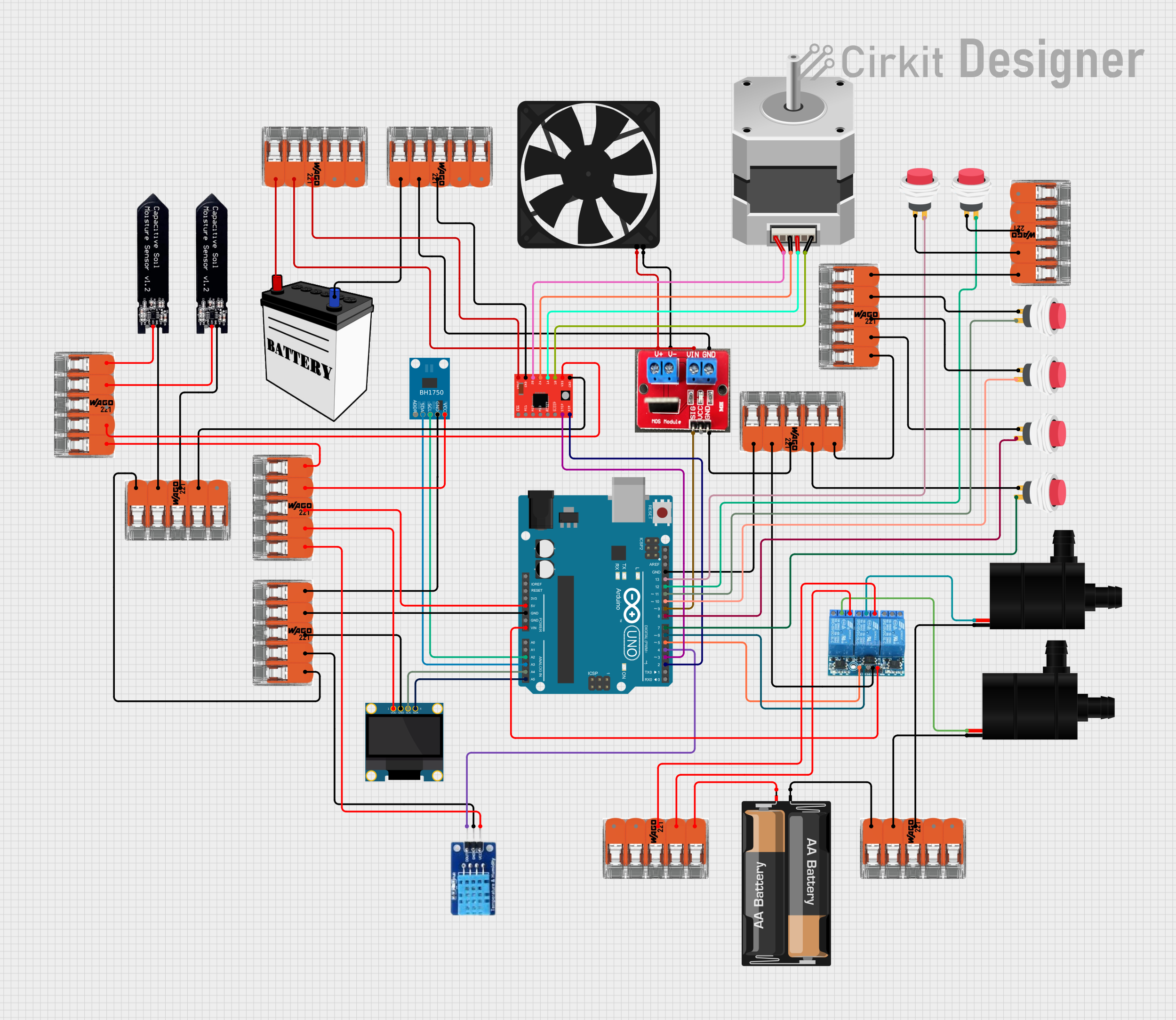
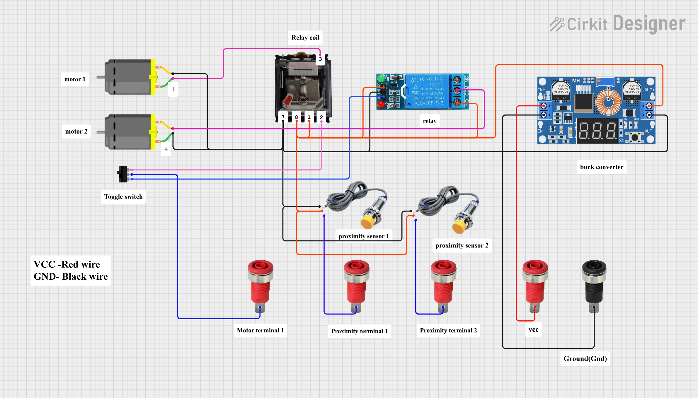
Explore Projects Built with Relay Omron MY2N
Common Applications and Use Cases
- Industrial automation and control systems
- Home appliances and HVAC systems
- Motor control circuits
- Signal switching in communication devices
- Power management in renewable energy systems
Technical Specifications
The following table outlines the key technical specifications of the Omron MY2N relay:
| Parameter | Value |
|---|---|
| Coil Voltage | 6V, 12V, 24V, 48V, 110V, 220V DC/AC |
| Contact Configuration | DPDT (Double Pole Double Throw) |
| Contact Rating | 5A at 250VAC / 30VDC |
| Coil Resistance | Varies by coil voltage (e.g., 160Ω for 24V DC) |
| Operating Time | Approx. 20 ms |
| Release Time | Approx. 20 ms |
| Insulation Resistance | 100 MΩ minimum (at 500VDC) |
| Dielectric Strength | 2000VAC between coil and contacts |
| Mechanical Durability | 50 million operations (minimum) |
| Electrical Durability | 500,000 operations (minimum) |
| Ambient Operating Temperature | -55°C to 70°C |
| Dimensions | 27.5mm x 21.5mm x 35.5mm |
Pin Configuration and Descriptions
The Omron MY2N relay has 8 pins, as described in the table below:
| Pin Number | Description |
|---|---|
| 1 | Coil Terminal A |
| 2 | Coil Terminal B |
| 3 | Common Contact (Pole 1) |
| 4 | Normally Closed (NC) Contact (Pole 1) |
| 5 | Normally Open (NO) Contact (Pole 1) |
| 6 | Common Contact (Pole 2) |
| 7 | Normally Closed (NC) Contact (Pole 2) |
| 8 | Normally Open (NO) Contact (Pole 2) |
Usage Instructions
How to Use the Omron MY2N Relay in a Circuit
- Power the Coil: Connect the coil terminals (pins 1 and 2) to the appropriate voltage source. Ensure the voltage matches the relay's rated coil voltage.
- Connect the Load:
- For each pole, connect the load to the common contact (pins 3 and 6).
- Use the normally open (NO) contact (pins 5 and 8) if you want the circuit to close when the relay is energized.
- Use the normally closed (NC) contact (pins 4 and 7) if you want the circuit to open when the relay is energized.
- Control the Relay: Use a microcontroller, switch, or other control device to energize the coil and toggle the relay's state.
Important Considerations and Best Practices
- Diode Protection: When using the relay with a DC coil, connect a flyback diode across the coil terminals to protect the driving circuit from voltage spikes caused by inductive kickback.
- Current Ratings: Ensure the load current does not exceed the relay's contact rating (5A).
- Mounting: Use a compatible socket or PCB mount for secure installation.
- Isolation: Maintain proper isolation between the coil and contact circuits to prevent interference.
Example: Using the MY2N Relay with an Arduino UNO
Below is an example of how to control the Omron MY2N relay using an Arduino UNO:
// Example: Controlling Omron MY2N Relay with Arduino UNO
// Pin 7 is used to control the relay

const int relayPin = 7; // Define the pin connected to the relay module

void setup() {
  pinMode(relayPin, OUTPUT); // Set relay pin as output
  digitalWrite(relayPin, LOW); // Ensure relay is off at startup
}

void loop() {
  digitalWrite(relayPin, HIGH); // Energize the relay (turn it on)
  delay(1000); // Keep the relay on for 1 second
  digitalWrite(relayPin, LOW); // De-energize the relay (turn it off)
  delay(1000); // Keep the relay off for 1 second
}
Note: Use a relay driver circuit (e.g., a transistor or relay module) to interface the Arduino with the MY2N relay, as the Arduino's GPIO pins cannot directly supply the required current for the relay coil.
Troubleshooting and FAQs
Common Issues and Solutions
Relay Not Switching:
- Cause: Insufficient coil voltage or current.
- Solution: Verify the power supply voltage and ensure it matches the relay's rated coil voltage.
Contacts Not Conducting Properly:
- Cause: Dirty or worn-out contacts.
- Solution: Clean the contacts or replace the relay if necessary.
Excessive Heat:
- Cause: Overloading the relay contacts.
- Solution: Ensure the load current does not exceed the relay's contact rating.
Noise or Chattering:
- Cause: Unstable control signal or insufficient coil voltage.
- Solution: Check the control circuit and stabilize the power supply.
FAQs
Q: Can the MY2N relay switch both AC and DC loads?
- A: Yes, the MY2N relay can switch both AC and DC loads, provided the load voltage and current are within the specified ratings.
Q: Is the MY2N relay suitable for high-frequency switching?
- A: No, the MY2N relay is not designed for high-frequency switching. For such applications, consider using a solid-state relay (SSR).
Q: Can I use the MY2N relay without a socket?
- A: Yes, the relay can be soldered directly onto a PCB, but using a socket is recommended for easy replacement.
Q: Does the MY2N relay have built-in protection?
- A: No, the relay does not have built-in protection. Use external components like diodes or snubber circuits for protection.
This concludes the documentation for the Omron MY2N relay.