How to Use TF LUNA LIDAR: Examples, Pinouts, and Specs
Introduction
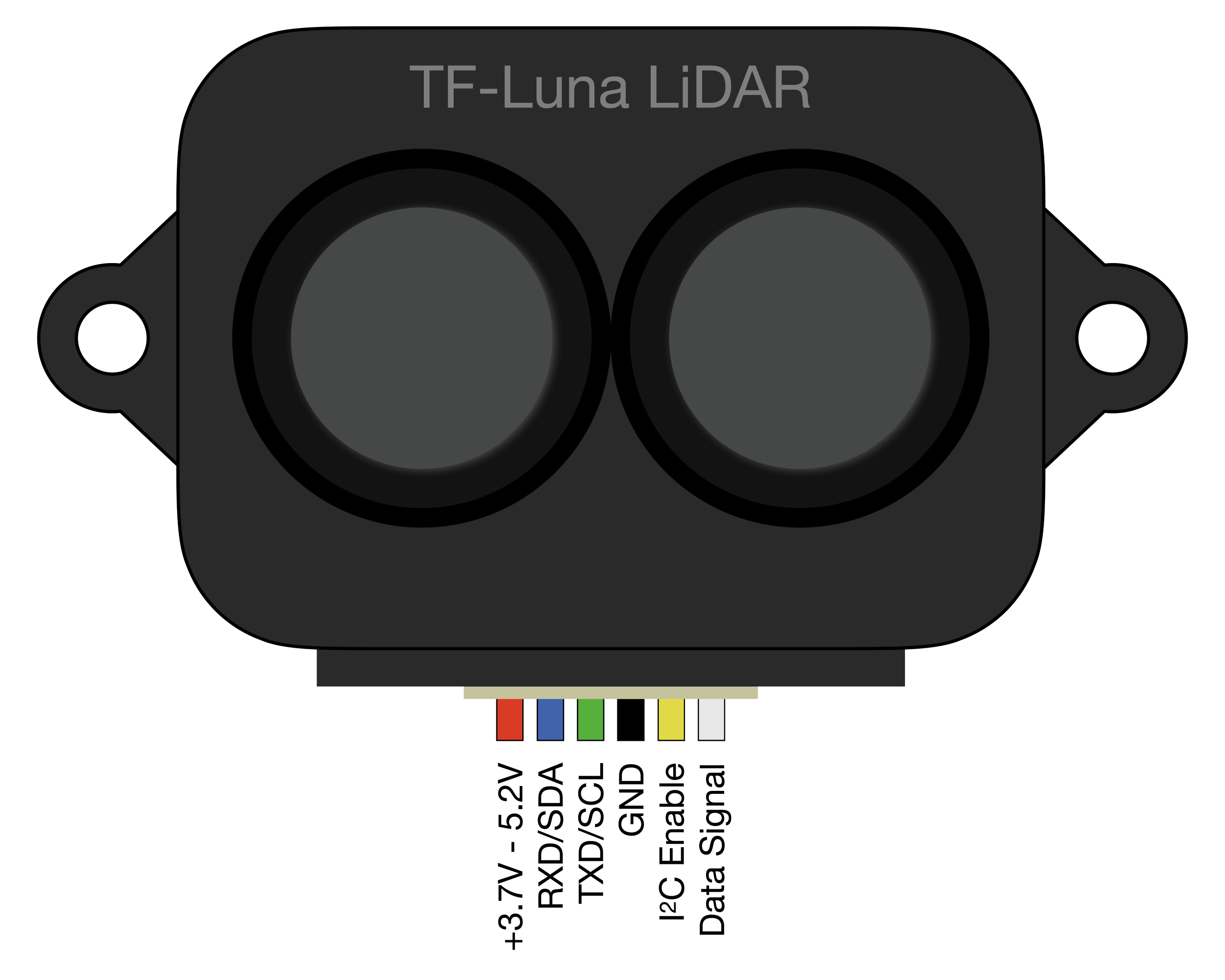
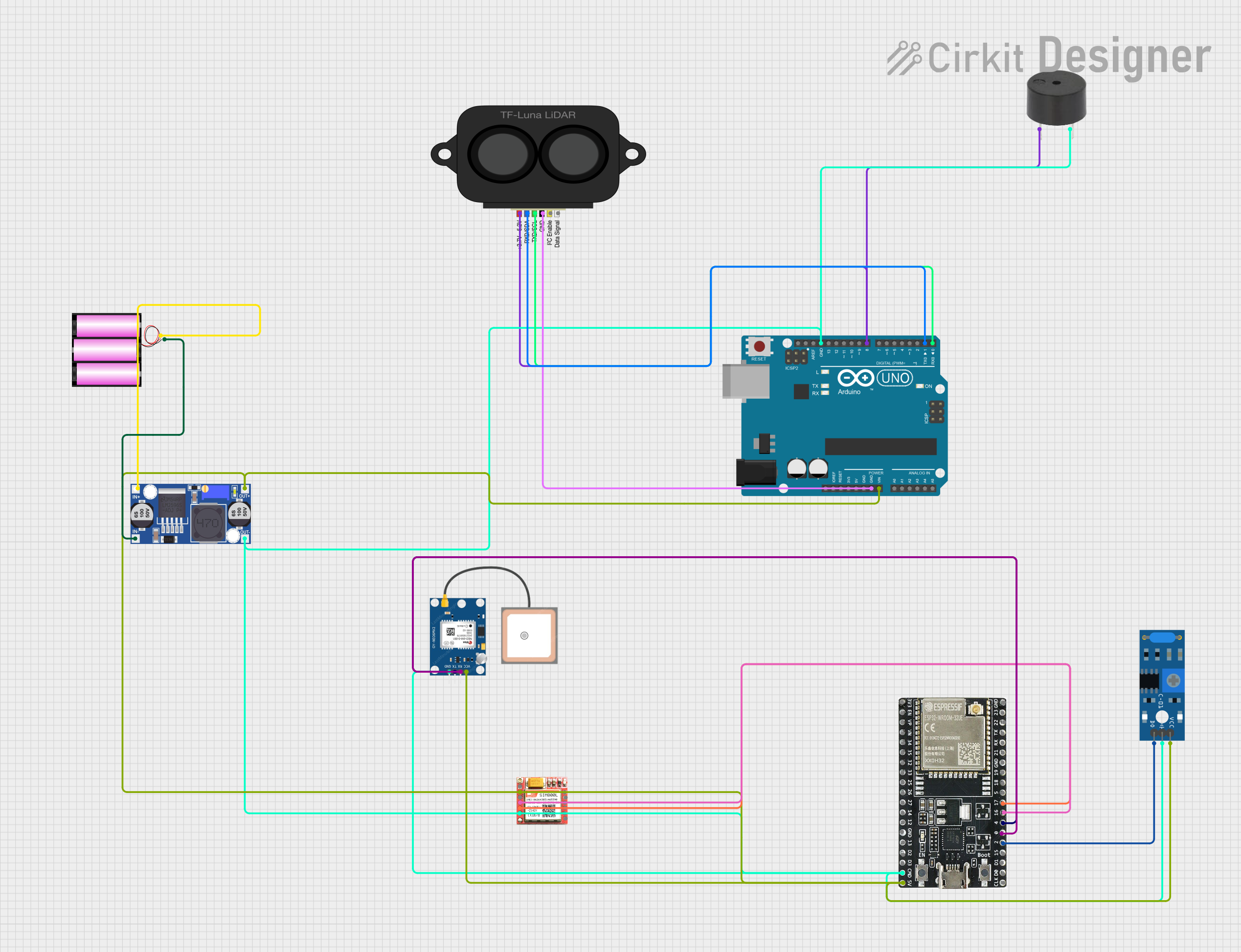
The TF Luna LiDAR is a compact Time-of-Flight (ToF) sensor designed for distance measurement and obstacle detection. Utilizing LiDAR technology, it emits laser pulses and measures the time it takes for the reflected signal to return, calculating the distance to an object. This sensor is widely used in robotics, drones, and various automation applications where precise distance measurement is crucial.
Explore Projects Built with TF LUNA LIDAR
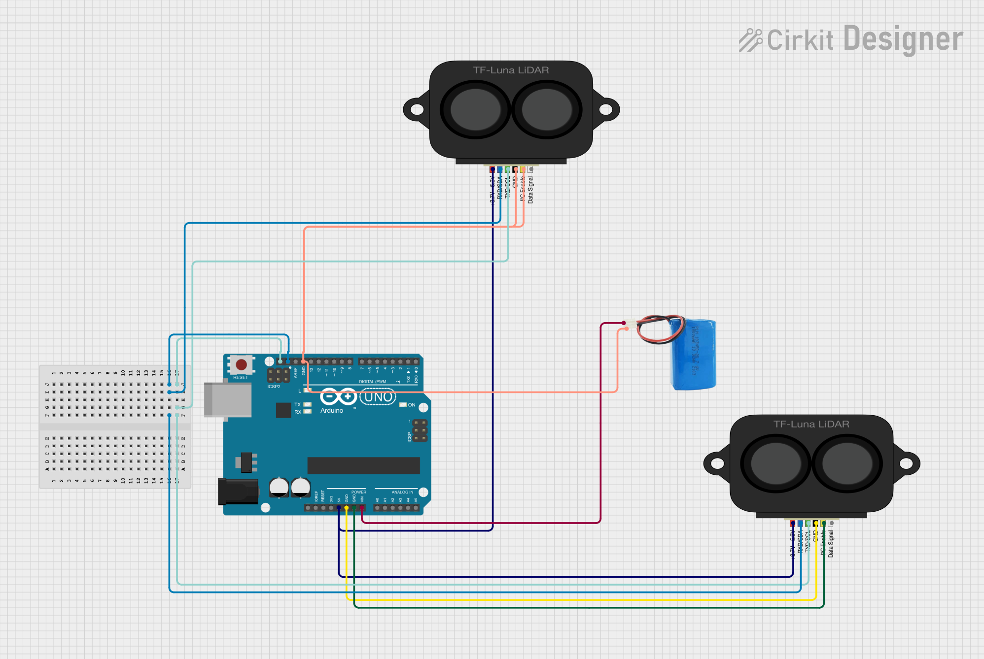
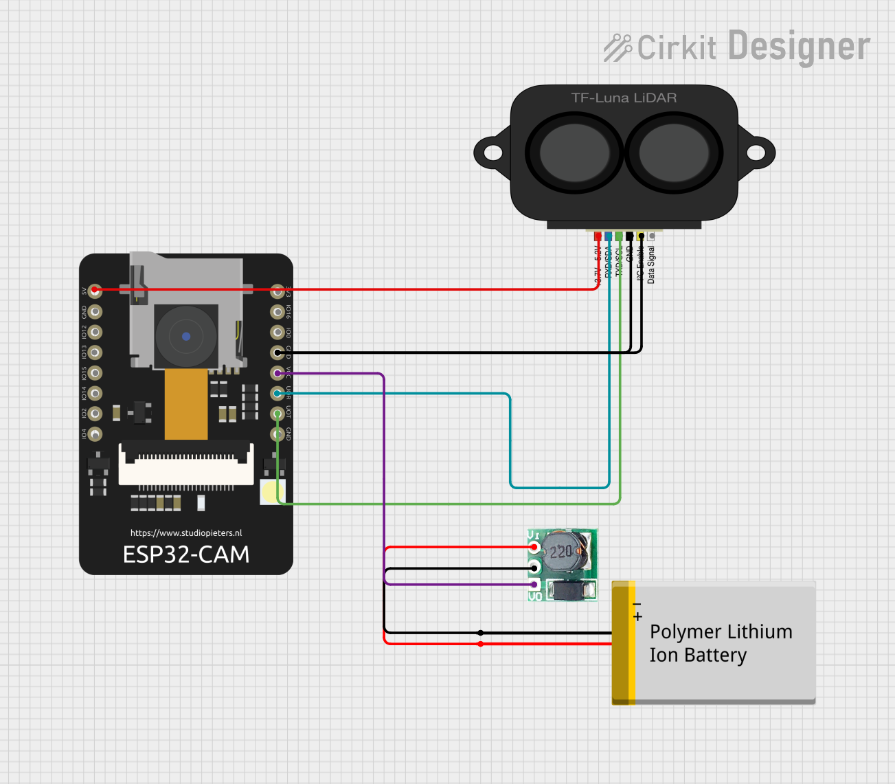
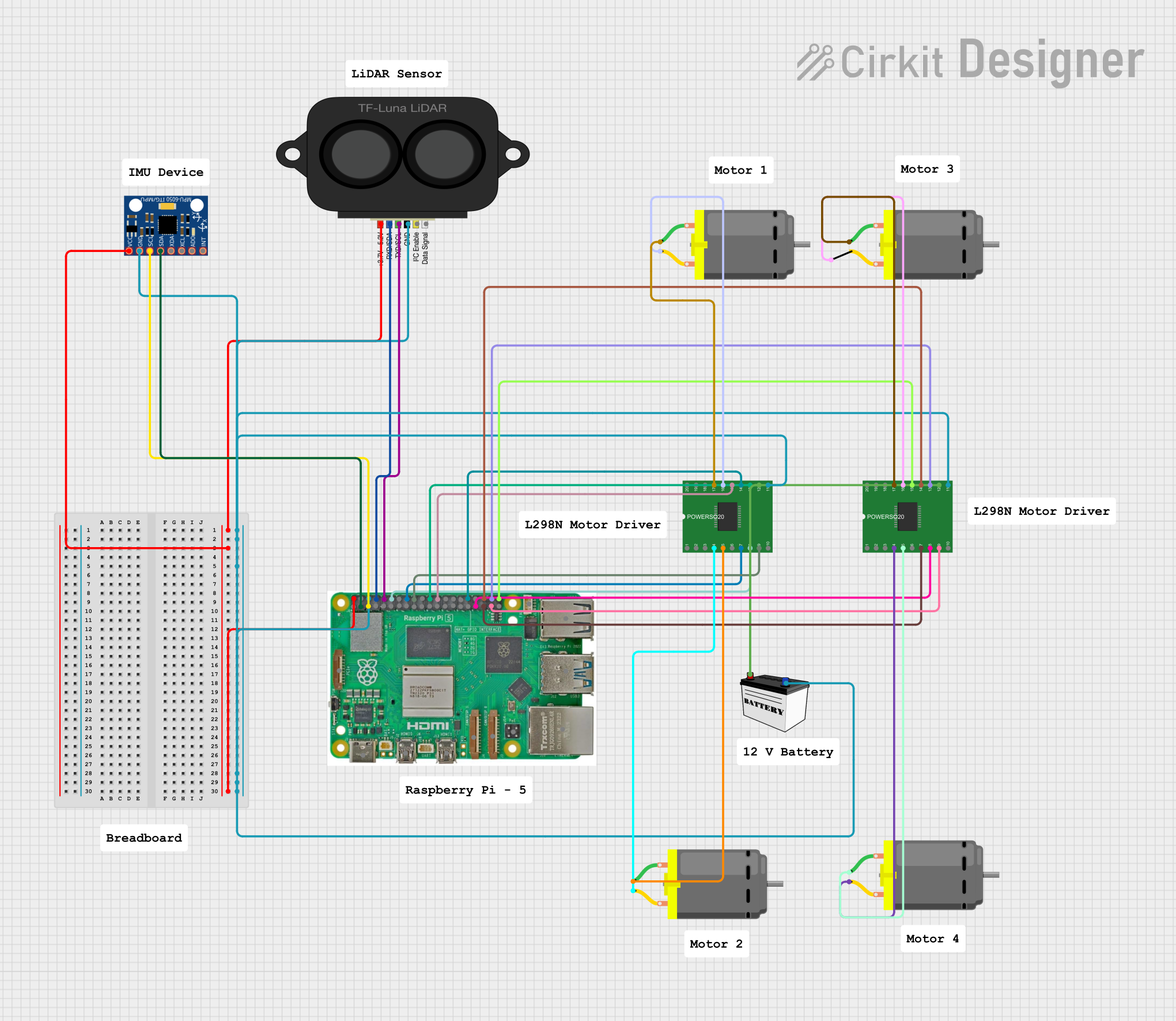
Explore Projects Built with TF LUNA LIDAR
Common Applications and Use Cases
- Robotics: obstacle avoidance, navigation
- Drones: altitude holding, terrain following
- Automation: level sensing, proximity alerts
- Smart devices: gesture recognition, user interaction
Technical Specifications
Key Technical Details
- Operating Voltage: 5V DC
- Average Current Consumption: 100 mA
- Peak Current Consumption: 150 mA
- Measurement Range: 0.2 to 8 meters
- Resolution: 1 cm
- Light Source: 850 nm VCSEL
- Laser Class: Class 1 (safe for eyes)
- Interface: UART/I2C
- Operating Temperature: -20°C to 60°C
Pin Configuration and Descriptions
| Pin Number | Name | Description |
|---|---|---|
| 1 | VCC | Power supply (5V DC) |
| 2 | GND | Ground |
| 3 | TX | UART Transmit (connect to RX of MCU) |
| 4 | RX | UART Receive (connect to TX of MCU) |
| 5 | SCL | I2C Clock (optional use) |
| 6 | SDA | I2C Data (optional use) |
Usage Instructions
How to Use the Component in a Circuit
- Connect the VCC pin to a 5V power supply.
- Connect the GND pin to the ground of the power supply.
- For UART communication, connect the TX pin of the TF Luna to the RX pin of the microcontroller (MCU), and the RX pin to the MCU's TX pin.
- For I2C communication, connect the SCL and SDA pins to the corresponding I2C clock and data lines on the MCU.
Important Considerations and Best Practices
- Ensure that the power supply is stable and within the specified voltage range.
- Avoid exposing the sensor to direct sunlight or strong reflective surfaces to prevent measurement errors.
- Keep the sensor lens clean and free from obstructions.
- When integrating with an MCU like Arduino, ensure that the serial baud rate matches the TF Luna's default setting.
Example Code for Arduino UNO
#include <SoftwareSerial.h>

SoftwareSerial tfLunaSerial(10, 11); // RX, TX

void setup() {
  Serial.begin(9600);
  tfLunaSerial.begin(115200); // TF Luna default baud rate
}

void loop() {
  if (tfLunaSerial.available()) {
    uint8_t data[9];
    if (tfLunaSerial.read() == 0x59) { // Frame header
      data[0] = 0x59;
      for (int i = 1; i < 9; i++) {
        data[i] = tfLunaSerial.read();
      }
      if (data[8] == (byte)(data[0] + data[1] + data[2] + data[3] + data[4] + data[5] + data[6] + data[7])) {
        int distance = data[2] + data[3] * 256; // Calculate distance
        Serial.print("Distance: ");
        Serial.print(distance);
        Serial.println("mm");
      }
    }
  }
}
Troubleshooting and FAQs
Common Issues Users Might Face
- Inaccurate Readings: Ensure there are no reflective surfaces or obstacles interfering with the sensor's line of sight.
- No Data Output: Check the wiring and connections, and ensure the correct baud rate is set for UART communication.
- Intermittent Readings: Verify that the power supply is stable and within the recommended voltage range.
Solutions and Tips for Troubleshooting
- If the readings are unstable, try adding a capacitor across the power supply lines close to the sensor to filter out noise.
- For issues related to data communication, use an oscilloscope to check the signal integrity of the UART or I2C lines.
- Ensure the MCU's serial buffer is read frequently enough to prevent overflow and missed readings.
FAQs
Q: Can the TF Luna LiDAR sensor be used outdoors? A: Yes, but direct sunlight may affect the accuracy of the sensor. It's best used in shaded or indoor environments.
Q: Is the TF Luna LiDAR sensor waterproof? A: No, the TF Luna is not waterproof and should be protected from moisture and water damage.
Q: What is the maximum baud rate for UART communication? A: The TF Luna supports a baud rate of up to 115200 bps for UART communication.
Q: How can I change the communication interface from UART to I2C? A: The TF Luna can be configured to use I2C by connecting the SCL and SDA pins and using the appropriate library or code to communicate via the I2C protocol.