Cirkit Designer Logo
Cirkit Designer
Your all-in-one circuit design IDE
Home / 
Component Documentation

How to Use Breadboard Power Module (3.3/5V): Examples, Pinouts, and Specs

Image of Breadboard Power Module (3.3/5V)
Cirkit Designer LogoDesign with Breadboard Power Module (3.3/5V) in Cirkit Designer

Introduction

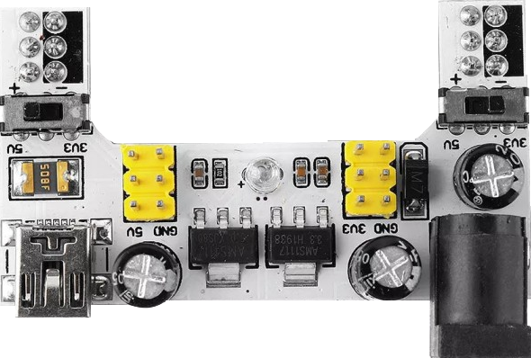
The Breadboard Power Module is an essential tool for hobbyists, students, and professionals working on electronic prototyping and testing. This device is designed to supply power to a breadboard circuit, offering both 3.3V and 5V output voltages, which are common requirements for a wide range of electronic components and microcontrollers. Its ease of use and versatility make it a staple in electronic labs and workshops.

Explore Projects Built with Breadboard Power Module (3.3/5V)

Use Cirkit Designer to design, explore, and prototype these projects online. Some projects support real-time simulation. Click "Open Project" to start designing instantly!
Battery-Powered Arduino UNO and ESP-8266 Smart Controller with LCD and RTC
Image of Ogie Diagram: A project utilizing Breadboard Power Module (3.3/5V) in a practical application
This circuit is a power management and control system that uses a 12V power supply and a 18650 Li-ion battery pack to provide a stable 5V output through a step-down buck converter. It includes an Arduino UNO, an ESP-8266 controller, a DS1307 RTC module, and a 20x4 I2C LCD display for monitoring and control purposes. The ULN2003A breakout board is used for driving higher current loads.
Cirkit Designer LogoOpen Project in Cirkit Designer
Battery-Powered 18650 Li-ion Charger with USB Output and Adjustable Voltage Regulator
Image of Breadboard: A project utilizing Breadboard Power Module (3.3/5V) in a practical application
This circuit is a battery management and power supply system that uses three 3.7V batteries connected to a 3S 10A Li-ion 18650 Charger Protection Board Module for balanced charging and protection. The system includes a TP4056 Battery Charging Protection Module for additional charging safety, a Step Up Boost Power Converter to regulate and boost the voltage, and a USB regulator to provide a stable 5V output, controlled by a push switch.
Cirkit Designer LogoOpen Project in Cirkit Designer
Arduino UNO RFID Access Control System with LCD Feedback and Servo Operation
Image of door lock: A project utilizing Breadboard Power Module (3.3/5V) in a practical application
This circuit features an Arduino UNO as the central microcontroller, interfaced with an RFID-RC522 module for RFID reading capabilities, and a 16x2 LCD screen with I2C for display. It also includes a 4x4 membrane matrix keypad for user input, a buzzer for audio feedback, and two Tower Pro SG90 servos for actuation. The MB102 Breadboard Power Supply Module provides power to the servos, while the Arduino powers the other components.
Cirkit Designer LogoOpen Project in Cirkit Designer
DC-DC Converter and Relay Module Power Distribution System
Image of relay: A project utilizing Breadboard Power Module (3.3/5V) in a practical application
This circuit consists of a DC-DC converter powering a 6-channel power module, which in turn supplies 5V to a 2-relay module. The power module distributes the converted voltage to the relay module, enabling it to control external devices.
Cirkit Designer LogoOpen Project in Cirkit Designer

Explore Projects Built with Breadboard Power Module (3.3/5V)

Use Cirkit Designer to design, explore, and prototype these projects online. Some projects support real-time simulation. Click "Open Project" to start designing instantly!
Image of Ogie Diagram: A project utilizing Breadboard Power Module (3.3/5V) in a practical application
Battery-Powered Arduino UNO and ESP-8266 Smart Controller with LCD and RTC
This circuit is a power management and control system that uses a 12V power supply and a 18650 Li-ion battery pack to provide a stable 5V output through a step-down buck converter. It includes an Arduino UNO, an ESP-8266 controller, a DS1307 RTC module, and a 20x4 I2C LCD display for monitoring and control purposes. The ULN2003A breakout board is used for driving higher current loads.
Cirkit Designer LogoOpen Project in Cirkit Designer
Image of Breadboard: A project utilizing Breadboard Power Module (3.3/5V) in a practical application
Battery-Powered 18650 Li-ion Charger with USB Output and Adjustable Voltage Regulator
This circuit is a battery management and power supply system that uses three 3.7V batteries connected to a 3S 10A Li-ion 18650 Charger Protection Board Module for balanced charging and protection. The system includes a TP4056 Battery Charging Protection Module for additional charging safety, a Step Up Boost Power Converter to regulate and boost the voltage, and a USB regulator to provide a stable 5V output, controlled by a push switch.
Cirkit Designer LogoOpen Project in Cirkit Designer
Image of door lock: A project utilizing Breadboard Power Module (3.3/5V) in a practical application
Arduino UNO RFID Access Control System with LCD Feedback and Servo Operation
This circuit features an Arduino UNO as the central microcontroller, interfaced with an RFID-RC522 module for RFID reading capabilities, and a 16x2 LCD screen with I2C for display. It also includes a 4x4 membrane matrix keypad for user input, a buzzer for audio feedback, and two Tower Pro SG90 servos for actuation. The MB102 Breadboard Power Supply Module provides power to the servos, while the Arduino powers the other components.
Cirkit Designer LogoOpen Project in Cirkit Designer
Image of relay: A project utilizing Breadboard Power Module (3.3/5V) in a practical application
DC-DC Converter and Relay Module Power Distribution System
This circuit consists of a DC-DC converter powering a 6-channel power module, which in turn supplies 5V to a 2-relay module. The power module distributes the converted voltage to the relay module, enabling it to control external devices.
Cirkit Designer LogoOpen Project in Cirkit Designer

Common Applications and Use Cases

  • Powering microcontrollers like Arduino, ESP8266, and Raspberry Pi GPIO circuits
  • Supplying power to sensors, LEDs, and other electronic components during prototyping
  • Providing a stable power source for analog and digital circuit testing

Technical Specifications

Key Technical Details

  • Input Voltage: 6.5V to 12V DC
  • Output Voltage: 3.3V and 5V (Selectable)
  • Maximum Output Current:
    • 3.3V - 700 mA
    • 5V - 1 A
  • Onboard USB Type-A port for power supply
  • Power Switch: Yes
  • Indicator LEDs: Power status indicators for 3.3V and 5V outputs

Pin Configuration and Descriptions

Pin Number Description Voltage/Signal
1 Ground (GND) 0V
2 Output Voltage (Vout) 3.3V or 5V
3 Voltage Selector (VS) Selects Vout
4 Input Voltage (Vin) 6.5V to 12V DC

Usage Instructions

How to Use the Component in a Circuit

  1. Connect the power module to the breadboard, ensuring proper alignment with the power rails.
  2. Set the voltage selector (VS) to the desired output voltage (3.3V or 5V).
  3. Connect the input voltage (Vin) to a DC power supply ranging from 6.5V to 12V.
  4. Use the onboard power switch to turn on the module.
  5. The power status LEDs will light up to indicate that the module is operational.
  6. Connect your electronic components to the breadboard, using the power rails supplied by the module.

Important Considerations and Best Practices

  • Verify the input voltage does not exceed the maximum rating of 12V to prevent damage.
  • Ensure the total current draw from the module does not exceed the maximum output current ratings.
  • When working with sensitive components, start with a lower voltage to prevent accidental damage.
  • Always turn off the power when making changes to your circuit to avoid shorts and component damage.

Troubleshooting and FAQs

Common Issues Users Might Face

  • No Power Output: Ensure the input voltage is connected and within the specified range. Check the power switch is turned on.
  • Insufficient Voltage or Current: Verify that the power supply can deliver sufficient current and that the voltage selector is set correctly.
  • Overheating: If the module becomes too hot, reduce the load or check for shorts in the circuit.

Solutions and Tips for Troubleshooting

  • Double-check all connections for correctness and firmness.
  • Use a multimeter to measure the input and output voltages to ensure they are within specifications.
  • If the module fails to power up, disconnect all components and test the module independently.

FAQs

Q: Can I use this module to power an Arduino UNO? A: Yes, you can set the output to 5V to power an Arduino UNO through its 5V pin.

Q: What should I do if the module is not supplying enough current? A: Ensure that the power supply connected to the input can provide enough current. If the issue persists, the module may be faulty.

Q: Is it possible to get both 3.3V and 5V at the same time? A: No, the voltage selector allows for only one output voltage at a time.

Example Arduino UNO Connection Code

// This example demonstrates how to power an Arduino UNO using the Breadboard Power Module.

void setup() {
  // Initialize the digital pin as an output.
  pinMode(LED_BUILTIN, OUTPUT); // Most Arduino boards have an on-board LED
}

void loop() {
  digitalWrite(LED_BUILTIN, HIGH);   // Turn the LED on
  delay(1000);                       // Wait for a second
  digitalWrite(LED_BUILTIN, LOW);    // Turn the LED off
  delay(1000);                       // Wait for a second
}

// Note: Connect the 5V and GND outputs from the Breadboard Power Module
// to the 5V and GND pins on the Arduino UNO, respectively.

Remember to ensure that the voltage selector on the power module is set to 5V before connecting it to the Arduino UNO.