How to Use Adafruit MOSFET Driver: Examples, Pinouts, and Specs
Introduction
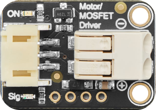
The Adafruit MOSFET Driver (Part ID: 5648) is a versatile module designed to control high-power devices using a low-power signal. This component is particularly useful in applications where microcontrollers, such as the Arduino UNO, need to drive motors, LEDs, and other high-current components. By leveraging the MOSFET Driver, users can efficiently manage power-hungry devices without overloading the microcontroller.
Explore Projects Built with Adafruit MOSFET Driver
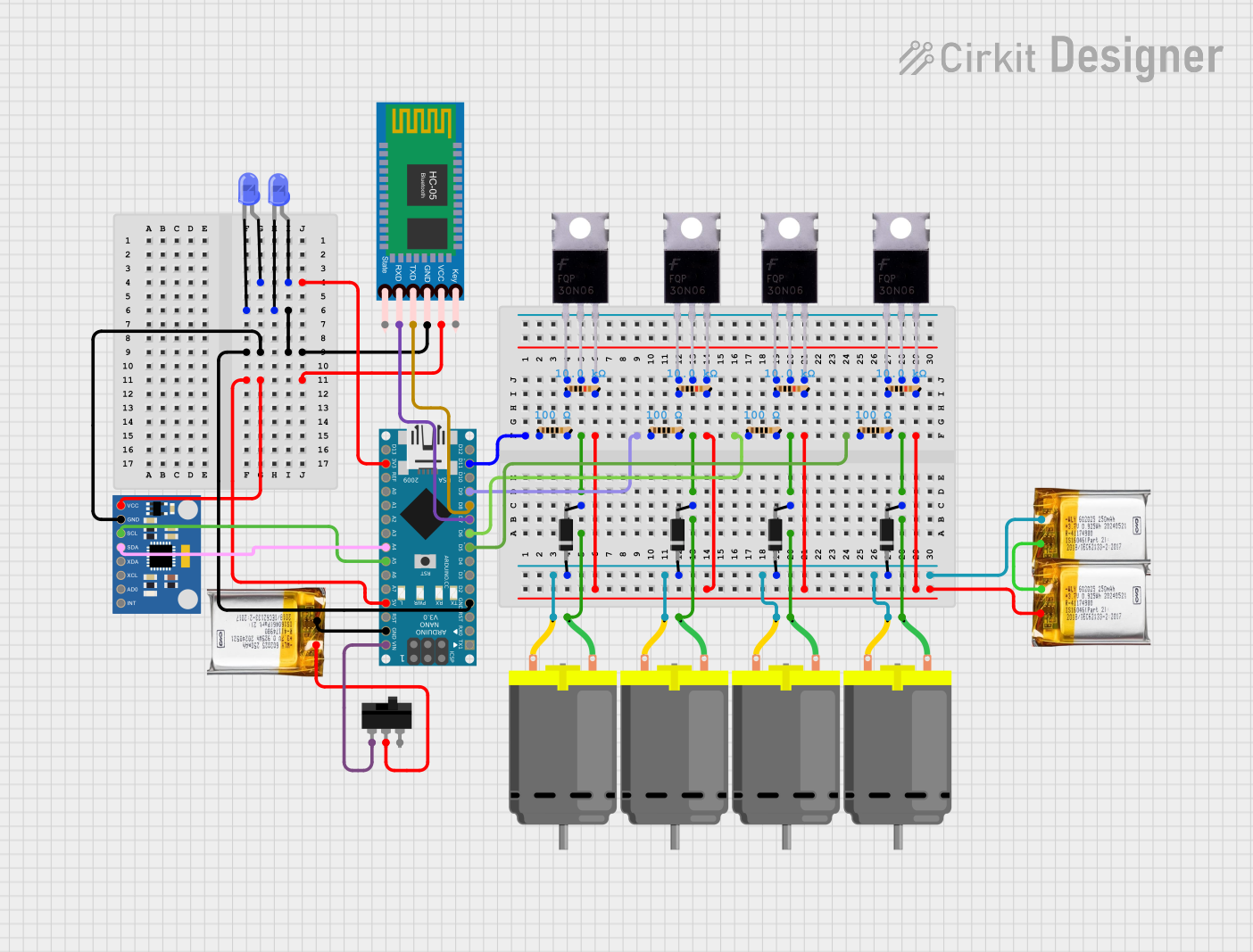


Explore Projects Built with Adafruit MOSFET Driver
Technical Specifications
Key Technical Details
| Parameter | Value |
|---|---|
| Manufacturer | Adafruit |
| Part ID | 5648 |
| Operating Voltage | 3.3V to 5V |
| Maximum Current | 30A |
| Maximum Voltage | 60V |
| Gate Threshold Voltage | 1V to 2V |
| On-Resistance (Rds) | 0.0075Ω |
| Package Type | Module |
Pin Configuration and Descriptions
| Pin Number | Pin Name | Description |
|---|---|---|
| 1 | GND | Ground connection |
| 2 | VCC | Power supply (3.3V to 5V) |
| 3 | IN | Control signal input from microcontroller |
| 4 | OUT | Output to high-power device |
| 5 | GND | Ground connection (connected internally to Pin 1) |
Usage Instructions
How to Use the Component in a Circuit
- Power Supply: Connect the VCC pin to the 3.3V or 5V power supply of your microcontroller.
- Ground: Connect the GND pins to the ground of your microcontroller.
- Control Signal: Connect the IN pin to a digital output pin of your microcontroller.
- Output: Connect the OUT pin to the high-power device you wish to control (e.g., motor, LED).
Important Considerations and Best Practices
- Heat Dissipation: Ensure proper heat dissipation when driving high-current loads. Use a heatsink if necessary.
- Gate Drive Voltage: Ensure the control signal voltage is within the specified range (3.3V to 5V).
- Current Limiting: Use appropriate current limiting techniques to prevent damage to the MOSFET Driver and the connected device.
- Isolation: For sensitive applications, consider using optocouplers to isolate the control signal from the high-power circuit.
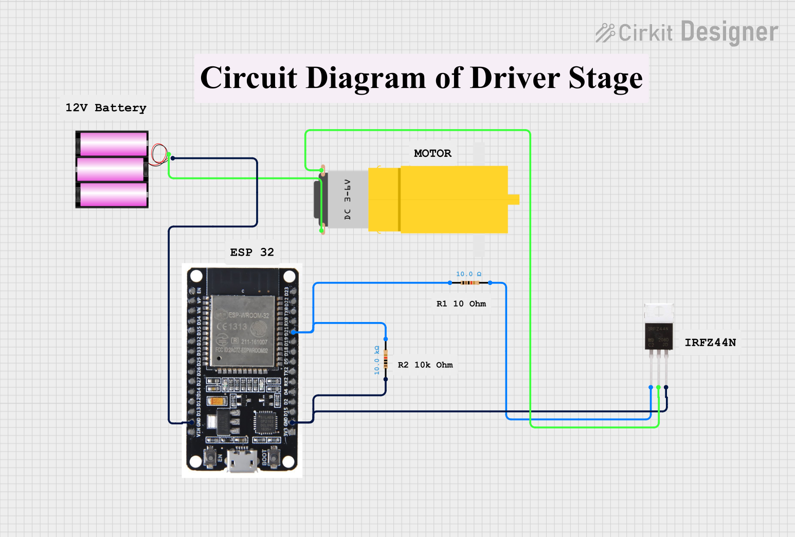
Example Circuit with Arduino UNO
/*
 * Example code to control a high-power LED using the Adafruit MOSFET Driver
 * and an Arduino UNO. The LED will blink on and off every second.
 */

const int controlPin = 9; // Digital pin connected to IN pin of MOSFET Driver

void setup() {
  pinMode(controlPin, OUTPUT); // Set the control pin as an output
}

void loop() {
  digitalWrite(controlPin, HIGH); // Turn on the high-power LED
  delay(1000);                    // Wait for 1 second
  digitalWrite(controlPin, LOW);  // Turn off the high-power LED
  delay(1000);                    // Wait for 1 second
}
Troubleshooting and FAQs
Common Issues Users Might Face
MOSFET Driver Not Turning On/Off:
- Solution: Check the control signal voltage. Ensure it is within the specified range (3.3V to 5V).
- Solution: Verify the connections, especially the ground connections.
Overheating:
- Solution: Ensure proper heat dissipation. Use a heatsink if necessary.
- Solution: Check the current draw of the connected device. Ensure it does not exceed the maximum current rating.
Inconsistent Operation:
- Solution: Check for loose connections or poor solder joints.
- Solution: Ensure the power supply is stable and within the specified voltage range.
FAQs
Q1: Can I use the Adafruit MOSFET Driver with a 12V power supply?
- A1: Yes, the MOSFET Driver can handle up to 60V on the output side. Ensure the control signal voltage is within the 3.3V to 5V range.
Q2: What type of devices can I control with the Adafruit MOSFET Driver?
- A2: You can control various high-power devices such as motors, high-power LEDs, solenoids, and other high-current components.
Q3: Do I need a heatsink for the MOSFET Driver?
- A3: It depends on the current draw of the connected device. For high-current applications, a heatsink is recommended to prevent overheating.
Q4: Can I use PWM signals with the Adafruit MOSFET Driver?
- A4: Yes, the MOSFET Driver can handle PWM signals, allowing you to control the speed of motors or the brightness of LEDs.
By following this documentation, users can effectively utilize the Adafruit MOSFET Driver to control high-power devices with ease and reliability.